My microwave oven started to malfunction at around five years old. It started to randomly power on the lamp, fan, and turntable. It progressively got worse over several weeks until it was mostly stuck on. The microwave oven is not usable when this happens: It behaves as if the door were open, causing the control panel to ignore button input and to stop cooking if it was cooking.
The obvious suspect is a failing door switch, which is a common cause of failure. There are three switches in the door, and a failure of one or more of them can cause strange behaviour when not all three switches agree on whether the door is open or closed. However, all three switches were tested to be in good working condition, so the most obvious reason is not the cause of this failure.
My microwave is an Insignia NS-MW09SS8 (a Best Buy brand), which is manufactured by Midea (FCC ID: RSFXM925AYY), with model number EMXAUXX-05-K marked on the circuit board inside. There are many other brands/models that use the same internal components. Unlike most similar models, mine has a blue LED display.
Spontaneously turning on is apparently not an uncommon failure. The one-star reviews on the Best Buy website for this model has almost 40 reports of this exact symptom. Many people (unnecessarily) worried that spontaneously turning on was a fire hazard. None of them seem to have found the root cause.
What went wrong?
The microwave “turning on by itself” was caused by an aging/failing LED display. Yes, really.
This unexpected conclusion is worth a blog post explaining exactly what went wrong, why it causes the observed symptoms, and how I repaired it.
This is a summary:
- If the lamp is on and the door is closed, the turntable and fan also turn on. The magnetron stays off, so there is no fire hazard. This is expected behaviour.
- The control board thought the door was open even when it is actually closed. This causes the lamp to turn on.
- This control board uses the same microcontroller GPIO pin to both drive segment A of the LED display and sense the door switch.
- Due to aging of the display’s LEDs, there is enough reverse-biased leakage through the LEDs to cause the door switch to be incorrectly sensed as open, causing the microcontroller to incorrectly think the door was open.
Microwave Oven Internals
Control Board
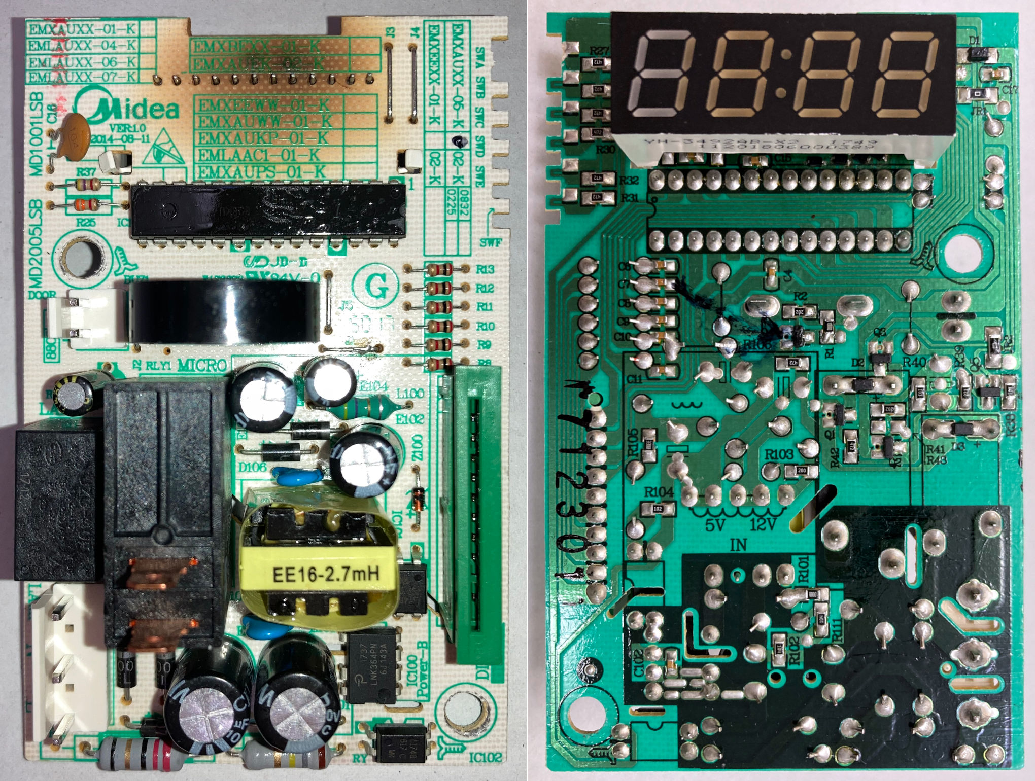
This is a photo of both sides of the control board. The burnt discolouration on the back side underneath the LED display is due to desoldering the display with hot air for repair.
Schematic
Here is a schematic for most of my microwave oven, reverse-engineered by following traces and cables. The schematic excludes the power supply section (switched-mode +5V and +12V supplies).

Lamp, Fan, and Turntable
Normally, when the door is open, the lamp turns on. When cooking, the lamp, fan, and turntable all turn on. What mechanism implements this behaviour, and how does it explain the malfunctioning behaviour where the lamp, fan, and turntable are all on?

Above is the portion of the circuit that controls the lamp, fan, turntable, and magnetron. Notice how there is only one relay (RLY2, turned on by Q2) that controls the lamp, fan and turntable. The microcontroller actually cannot independently control these. When the microcontroller turns on the lamp relay (RLY2), the upper door switch (not the microcontroller) decides whether only the lamp turns on, or all three.
In the failed state, the microcontroller thought the door was open (according to the lower door switch) and turned on the lamp (RLY2) in response. But the door was closed according to the upper door switch, so the fan and turntable also turn on when the lamp is turned on. This behaviour is expected, but what’s unexpected is the microcontroller detecting an open door when the door is actually closed.
An interesting side effect of this design is that if the door-open lever is slightly pressed, just enough to toggle only the bottom door switch, the lamp, fan, and turntable all turn on. This can occasionally cause surprise and lead the user to wonder if the microwave oven is unexpectedly cooking (It is not).
Door Switch Sensing
Why does the microcontroller think the door is open when it isn’t? How does the microcontroller sense whether the door is open?
This is the portion of the circuit that senses whether the lower door switch is closed (shorted to ground) or open. Although there are three door switches, the lower switch is the only one that informs the microcontroller about the state of the door.

The microcontroller pin “Port H.0” senses the door switch state. When the door switch is open (door open), R34 pulls the input pin (H.0) to +5V. When the door switch is closed (door closed), the input pin is pulled low (to about 0.6V, the forward voltage drop of the diode) through diode D1 and the door switch to ground. When microcontroller port H.0 is used as an input pin, we expect to see either +5V if the door is open, or around +0.6V if the door is closed.
D1 prevents any current from the magnetron relay (RLY1) from flowing through the microcontroller pin and accidentally turning on RLY1.
R33 exists because the same microcontroller input pin is shared with the LED display’s segment A (Notice how the Door_LEDA_H.0 signal is also connected to the LED display’s segment A). Sharing a pin between multiple functions reduces cost by reducing the number of I/O pins needed on the microcontroller. The microcontroller pin is set to drive either high or low when driving the LED display (8ms out of every 10ms), and is set to be a high-impedance input pin when it wants to sense the door switch. It is this pin sharing that causes the door switch to be incorrectly detected as open (high input voltage) despite the switch being closed. Sharing a pin allows a malfunctioning LED segment to disrupt the voltage when trying to sense the door switch.
When sensing the door switch, all four LED cathodes are pulled high (Ports D.0, D.1, A.2 and A.3), turning off all of the LEDs and putting them into reverse bias. When the door is closed, we expect PortH.0 to be a logic 0 (low voltage). But any reverse leakage current through any of the four segment A LEDs appears as a pull-up current applied directly to the input pin (port H.0) that must drain through the 2k-ohm R33. It doesn’t take much leakage current to raise the voltage on the input pin high enough to be detected as logic high.
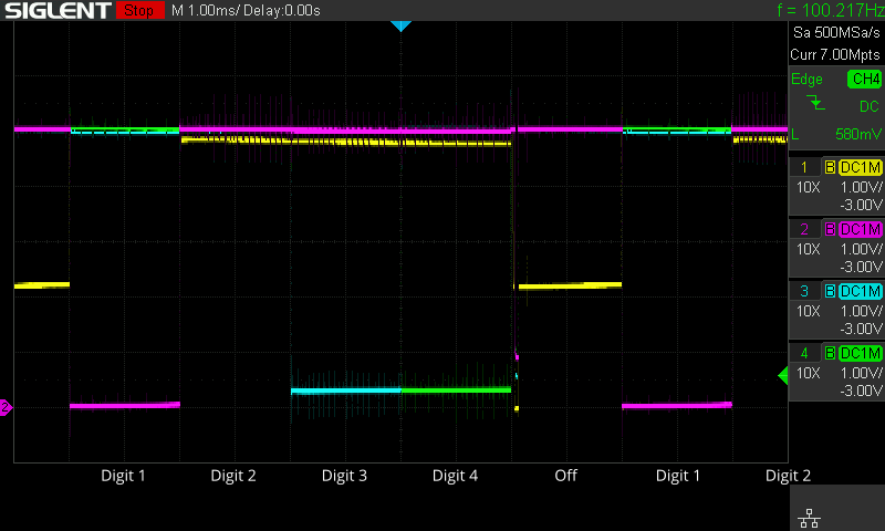
In the oscilloscope traces below, the door switch sensing happens in the 2ms when the LEDs are off (labelled “Off”). Notice that before the repair (top two plots), when the door is closed, the Port H.0 pin voltage (yellow trace) only drops to around 2.2V, even though the expected voltage is around 0.6V if there was no LED display leakage current. 2.2V is more than enough to be sensed as a logic high. (When the door is open, the Port H.0 input pin voltage is +5V, as expected.)
LED Display
The LED display is common cathode and has four digits and two independently-controlled dots (part of digits 3 and 4, respectively) that form a colon. Each digit is turned on in sequence (left to right) for two milliseconds each, followed by two milliseconds with all digits off. The cycle repeats every 10 milliseconds.
The LED display shares a pin with the door switch sense circuit and also shares six pins with the control panel buttons. The door switch sensing seems to happen during the two milliseconds when all LEDs are off.
| Door open | Door closed | |
|---|---|---|
| Before | 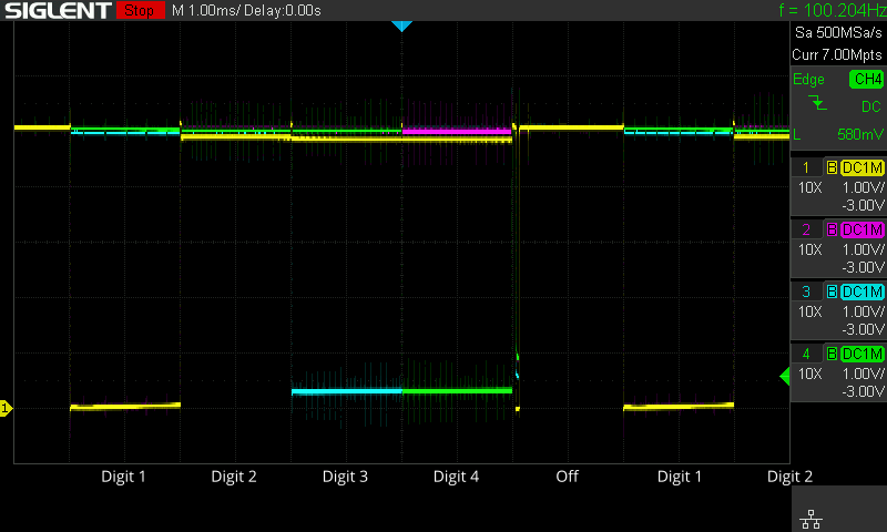 |
 |
| Repaired | 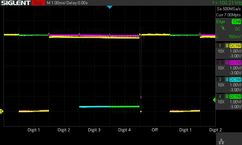 |
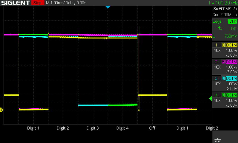 |
The four oscilloscope plots above capture 14 milliseconds (1 ms per grid square) showing the LED display being scanned, both with the door switch open and closed, before and after my repair. The yellow trace is microcontroller pin Port H.0, which drives LED segment A and senses the door switch. The other three traces show the cathode pin of some of the display digits (cyan = digit 1, magenta = digit 3, green = digit 4. I only have a 4-channel oscilloscope, so I omitted digit 2). Each LED digit is on when the cathode pin is low, so you can see each digit being turned on for two milliseconds each, followed by two milliseconds when all four digits are off. During the two milliseconds with the display off, Port H.0 (yellow trace) is set to be an input pin to sense the door switch.
Looking at the “Off” region, the two plots with the door open (left two plots, both before and after the repair) show +5V on the input pin, as expected. However, when the door is closed (upper-right plot), the voltage on pin Port H.0 only drops to +2.2V due to reverse leakage current through the display. This is high enough to be detected as a logic 1, so the microcontroller becomes unable to sense a closed door. After the repair (lower-right plot), the voltage on pin Port H.0 drops to around 1V when the door is closed (low enough to be sensed as logic 0), restoring normal functionality.
(When these traces were collected, the display was displaying 0:00, so segment A, the top horizontal LED of each digit (yellow oscilloscope trace), is high for digits 2, 3, and 4, but not digit 1).
Repair

Simple repair: Add a diode to block reverse leakage current on the pin that matters.
Repairing the door sense circuit is relatively easy (compared to finding the problem), requiring desoldering the display module, modifying some surface-mount components, and reinstalling the display. Since the main problem is reverse leakage on the segment A pin, I added a diode in series with the segment A LEDs (next to, and in series with R14) to prevent the leakage. I chose a schottky diode to minimize forward voltage drop and the reduction in brightness of segment A (Schottky diodes have lower forward voltage drop than silicon PN junction diodes). I could not visually notice any decrease in brightness.
However, this only prevents the failing LED display from interfering with the door switch sensing circuit, and doesn’t actually fix the aging display. On my display, segment A on digit 3 no longer lights up most of the time.
This failure could have been prevented had the original circuit added this one diode. If the circuit added diodes to all 12 pins of the LED display, the display aging might also be significantly reduced, because I suspect that applying 5V of reverse voltage across the LEDs contributes to its aging, and extra diodes in series prevents this. Most diodes can withstand higher reverse voltages than light-emitting diodes (LED).
Due to the LED display aging and failing, I will probably want to replace it eventually. The display is a 4-digit clock style (with a colon instead of decimal points) LED seven-segment display. But the pin arrangement is so unusual that I was not able to find a replacement. I will likely need to get displays with a different (and more standard) pin arrangement and design a circuit in between to connect up the pins.
More observations
Magnetron Failsafe
I’m quite impressed by how many independent mechanisms there are to prevent the magnetron from accidentally turning on. Not only are there three door switches to ensure the door is closed, there’s also a mechanism to guard against a faulty microcontroller or software.
The magnetron high voltage transformer is turned on by relay RLY1, which also goes through two mechanical switches (upper and middle door switches). If the upper switch detects an open door (open switch), the circuit is opened and there is no power to the magnetron. If the middle switch detects an open door (closed switch), the transformer is shorted out and you would get a short circuit and trip a circuit breaker (or possibly even melt a switch), but still no magnetron power. These two switches are in the 120V AC path, so they can protect against a faulty RLY1 that is stuck on.
The path that controls the magnetron relay RLY1 has three separate controls in series (Q1, Q3, and lower door switch). If the lower door switch detects an open door (open switch), RLY1 doesn’t turn on. Once the door is closed, two transistors (Q1 and Q3) both need to be on to enable RLY1. Q3 is directly controlled by the microcontroller to turn on the magnetron relay RLY1. But there is also Q1, which only allows RLY2 to turn on if the lamp relay (RLY2) has also been commanded to power on (by Q2).
Q2 is the transistor that responds to the microcontroller command to turn on the lamp relay (RLY2). But unlike Q3, Q2 is not directly connected to a microcontroller pin. It goes through Q5 and several passive components first. I believe these components are designed to prevent a malfunctioning microcontroller from causing the microwave oven to be stuck on. C16 blocks any DC signal, so to turn on Q2, the microcontroller must output a continuous pulse train to periodically turn on Q5 to charge up capacitor E1, which turns on Q2. If the microcontroller stops toggling the output pin (Port C.2) for any reason (hardware failure, software crash), Q2 turns off once E1 discharges (~20 ms?), making it impossible for the microcontroller to freeze with the lamp and magnetron stuck on.
Buttons
There are 24 buttons on the control panel, and what looks like 6 + 4 (row and column) wires leading to the control panel. Six of these wires are shared with the LED display anode wires. This probably means the buttons are scanned while the LED display is off (to allow freely toggling the anode wires without anything being shown on the display), but I haven’t attempted to figure out exactly which part of the 10ms cycle this happens.
Since six of the button wires are shared with the LED display, it seems plausible that reverse leakage current in the display can also affect the buttons. I’m not sure if this explains any of the reports of malfunctioning buttons in some of the reviews.
Clock…?
Port E.3 (Pin 1 of the SH69P26K microcontroller) connects to an optocoupler (IC102) that’s driven by the live wire of the AC input. This circuit looks like it is intended to generate a pulse once per AC cycle (60 Hz) going to the microcontroller. I suspect this signal is used as a 60 Hz clock to run the timer and clock. I haven’t attempted to test this hypothesis.
According to the datasheet, this microcontroller supports both internal and external oscillators, but this board seems to leave the OSCO and OSCI pins unconnected, which means the microcontroller is using the internal oscillator option. The internal oscillator is rated for up to 50% relative frequency error, nowhere near accurate enough for a clock. I’m surprised that they chose to add a bunch of components to feed the AC line frequency to the microcontroller instead of just using a 32.768 kHz crystal. A single crystal oscillator seems like both the cheaper and more accurate option, especially if someone were to take the microwave to a place that does not use 60 Hz mains frequency.
Model selection “switches”
There are six switches to select between similar models of microwave without needing a different board or software program. The six “switches” are actually small tabs in the circuit board that are snapped off to open the switch. For my microwave oven, SWA is snapped off. Four of these switches (SWA to SWD) share pins with the LEDs.
Conclusions
The “microwave turns itself on” failure is caused by a failing LED display causing the microcontroller to detect the door as open even when it is closed. This failure is possible due to sharing microcontroller I/O pins between different functions to cut cost, allowing malfunctions in one area to affect another. Sharing pins is probably not an uncommon thing to do, but the design should be more tolerant of LED reverse leakage current. This design vulnerability is compounded by the use of blue LEDs for the display, which fail more quickly than other colours (most commonly green).
- When designing an appliance, avoid sharing GPIO pins between LEDs and anything functionally important, or at least design it to tolerate a significant amount of reverse leakage current. LEDs can fail with age.
- If you’re buying a microwave oven, it’s fairly hard to know which models have this vulnerability: Midea makes a fairly large fraction of all microwave ovens, multiple Midea models have the same problem, but not all models do.
- But you can greatly improve your chances by avoiding blue LED displays.
Does display colour really matter?
Anecdotally, I’ve noticed that blue indicator LEDs tend to fail much more frequently than other colours. But is this observation also true here?
To find out whether display colour matters, I compiled a list of microwave models similar to mine that I’m fairly certain either use the same mainboard, or has a similar mainboard that most likely has the same vulnerability. Then I read through the one-star reviews (mainly people complaining about failures) and count how many of those reviews describe the microwave randomly turning on when the door is closed. I observe whether the colour of the display affects how often this failure mode shows up in one-star reviews. If blue displays really are less reliable, I should see more failures of this type for models with blue displays than for similar models with green displays. The following table summarizes the results.
It’s quite clear that all three models with blue displays have a much higher rate of failing by randomly turning on and off with the door closed. For one-star reviews, it is ~25 times more likely to get a complaint about spontaneously turning on when the LED display is blue compared to when it is green.
| Brand/Model | FCC ID | Mainboard Part Number | Display Colour | Total Reviews | One-star reviews | One star and randomly turning on |
Review Source |
|---|---|---|---|---|---|---|---|
| Insignia NS-MW09SS8 (mine) | RSFXM925AYY | 17170000006520 | Blue | 6789 | 244 | 37 | Best Buy |
| Sharp SMC0912BS | 291 | 54 | 29 | Lowe’s | |||
| Black & Decker EM925AAK-P | 17170000006520 | Green | 425 | 122 | 1 | Target | |
| Black & Decker EM925AB9 | 17170000006520 | 981 | 210 | 0 | Amazon | ||
| Black & Decker EM925AZE-P | 129 | 29 | 0 | Amazon | |||
| Emerson MW9325SL | |||||||
| Farberware FM09SSE | 128 | 17 | 0 | Amazon | |||
| Frigidaire FFCM0934LS | |||||||
| Hamilton Beach EM925A2CE-P1 | 690 | 81 | 2 | Walmart | |||
| High Pointe EM925ACW | |||||||
| Insignia NS-MW09BK0 | 478 | 23 | 1 | Best Buy | |||
| Insignia NS-MW09RD7 | |||||||
| Kenmore 405.73093310, 405.73099310, 405.73092310 | |||||||
| Pelonis EM925AFO-P2 | |||||||
| Salton MW2079 | |||||||
| Toshiba ML2-EM25PA(BS) | (~824/2) * | (~75/2) * | 1 | Lowe’s | |||
| Westbend EM925AJW-P2 ** | |||||||
| Westbend EM925AJW-P2 ** | VG8EM925AYY | ||||||
| Insignia NS-MW11BK0 | VG8XM031MYY | Blue | 2630 | 89 | 18 | Best Buy | |
| Black & Decker EM031MB11 | 17170000000832 | Green | 763 | 165 | 1 | Amazon | |
| GE JES1145SH1SS | 7659 | 280 | 5 | Home depot | |||
| Hamilton Beach EM031M2ZC-X3 | 2739 | 238 | 0 | Walmart | |||
| Toshiba ML2-EM31PA(SS) | (~824/2) * | (~75/2) * | 0 | Lowe’s | |||
| Black & Decker EM036AB14 | VG8XM036AYY | 17170000006520 | 220 | 45 | 1 | Amazon | |
| Toshiba EM925A5A-SS | VG8EM025FXXXV2 | 17170000006520 | 2470 | 431 | 3 | Amazon | |
| Toshiba ML2-EM09PA(BS) | White? | 317 | 55 | 1 | Amazon | ||
| Black & Decker EM720CB7 | VG8XM720CYY-PM | 17170000000832 | Green | 1316 | 355 | 3 | Amazon |
| Magic Chef HMM770B2 | 705 | 59 | 0 | Home depot | |||
| Midea MMC07S1ABB | 198 | 17 | 0 | Lowe’s | |||
| Sharp SMC0710BB | 395 | 11 | 0 | Lowe’s |
** The Westbend EM925AJW-P2 seems to be available with two different FCC IDs. The only difference between them appears to be the manufacturer of the magnetron (Witol vs. LG).
The FCC ID is useful for identifying models that should be substantially the same, even if they have cosmetically different styling. I’ve grouped microwave models by FCC ID in the table above. Models with the same FCC ID do have some mainboard variations over the years. The changes are usually small (otherwise the FCC ID would change), and I don’t know which mainboard revision was used for each customer review, so I don’t try to distinguish differences within the same model, if any.
Another source of information is from the mainboard part number: Some websites list which microwave models used that particular board, which tells me a set of models that share the same mainboard despite having different FCC ID, size, and power. I think it’s reasonable to assume that all models with the same FCC ID share the same mainboard (or revisions of it), but I only filled in the Mainboard Part Number in the table if I found some evidence of that mainboard being used in that particular model.
Leave a Reply