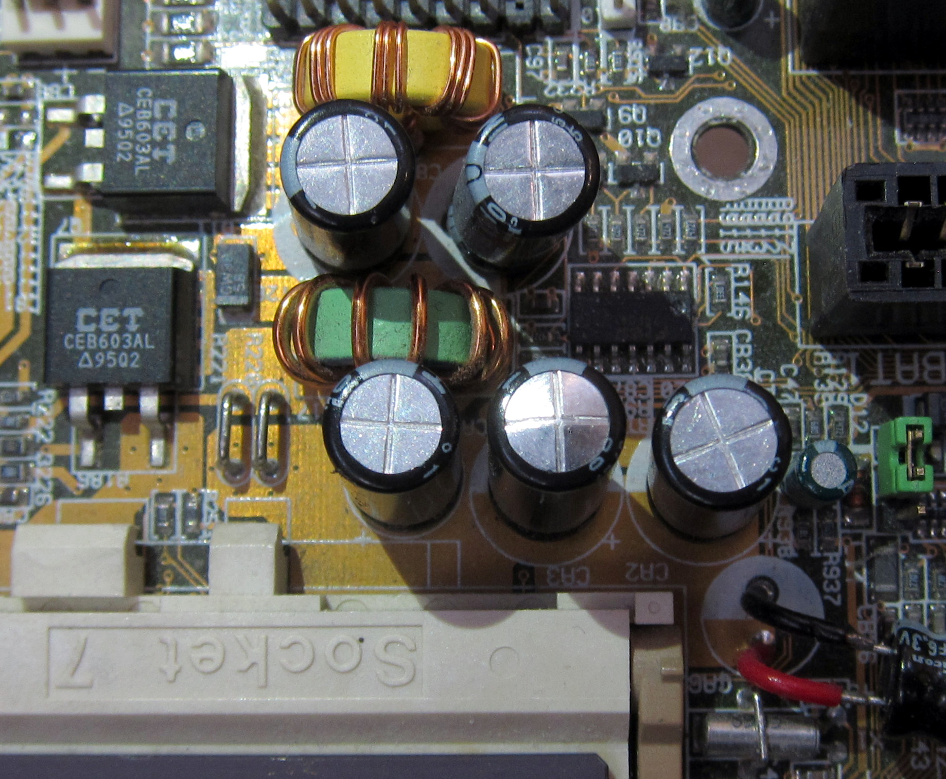
Five Nichicon HM capacitors from 2005 (one swollen) on a MS-5184 motherboard from 1999.
Capacitor plague. Swollen and leaking electrolytic capacitors. A well-known phenomenon since the early 2000s.
Caused by heat, ripple current, unknown brands, or Taiwanese origin? Not necessarily.
Back in 2006 (16 years ago), I bought some Nichicon HM series electrolytic capacitors to replace swollen capacitors on an old PC motherboard. I recently noticed that the replacement capacitors were swollen again, yet the motherboard had been almost unused since the last capacitor replacement. I still have most of the bag of 200, so I decided to investigate. Although they sat in a box unused, 70% of them were swollen…
Background: Capacitor Plague
Electrolytic capacitors sometimes fail by swelling. This was particularly common in the early 2000s and is often referred to as capacitor plague. These capacitors would generate gas and swell as they age, and eventually rupture and cause the failure of whatever electronic device was using it (often a power supply of some sort).
I had assumed that this only happened while in use, either holding a charge, or something to do with ripple current. But this assumption is incorrect, because I now have a large number of never-used (stored at room temperature) capacitors that swelled, including some that swelled enough to leak.
One of the well-known aging properties of electrolytic capacitors is that the oxide dielectric can become thinner if the capacitor is stored uncharged. This results in increased leakage current and increased capacitance. This is supposed to be reversible within some minutes by charging up the capacitor, which causes the oxide layer to grow back, in a process called reforming. But swelling and rupturing goes well beyond just a reversible increase in leakage current.
Starting in the late 1990s, a new generation of low-ESR capacitors began to use water-based electrolyte. Water-based electrolytes have the benefit of low-ESR that allows higher ripple currents, but comes with a risk of corrosion because water can react with aluminum and cause corrosion and hydrogen gas if corrosion inhibitors are not used correctly [1]. This corrosion is likely the cause of the capacitor plague. The Nichicon HM is a low-ESR capacitor from the affected time period (early 2000s) and seems to be failing with similar symptoms, so it’s likely that these failures are also due to the use of a water-based electrolyte without sufficient corrosion inhibitors.
Similar symptoms have been observed before (increased capacitance and leakage before rupture), and Hillman and Helmold performed a chemical analysis of the failing capacitors, finding dissolved aluminum in the electrolyte [2]. In addition to the known symptoms, I observed that my corroding capacitors appear to be turning into batteries and self-charging with a negative voltage, which does not appear to have been previously reported.
Capacitors tested
Nichicon HM

Nichicon HM 6.3V 1500µF, manufactured 2005 week 11.
- Nichicon HM 6.3V 1500µF (2005 week 11). Made in Japan.
Nichicon is a well-known Japanese manufacture of capacitors. Their HM series is an aluminum liquid electrolytic capacitor designed with low impedance (low-ESR) for use in PC motherboards. The HM and HN series were known for early failure. Although there were some claims that the problems were fixed in 2005, week 11 was likely still bad given how many failures I have.
Control group: Nichicon HZ and Kemet 759
I did measurements on two other capacitor models (that had no problems) to use as a control group.
- Nichicon HZ 10V 1000µF (2012 week 6). Advertised as a lower-impedance version of the HN series, which is a lower-impedance version of the HM.
- Kemet 759 10V 1500µF (2020 week 44). This is a solid polymer capacitor.
First attempt at basic measurements: Failed
I started by measuring the capacitance with my multimeter. This failed on all the capacitors, because the leakage was too high. A capacitance meter measures how long it takes to charge and discharge the capacitor, but if the leakage is too high, it will never charge enough to get a measurement.
The next thing to try was to charge the capacitor up to 5V through a current meter. Bad idea. The leakage current reached at least 1.5A (at least for a short moment), and the capacitor heated up and swelled very quickly. It’s good that I didn’t try powering on the motherboard, because this much leakage current could have caused some real damage.
In the remainder of the article, I visually sort the capacitors by whether it is swollen, then measure open-circuit voltage, charge up the capacitor in an attempt to reform the dielectric oxide layer, then measure capacitance and open-circuit voltage again.
Visually sorting by swelling
I sorted the capacitors visually by whether they appeared swollen. This allows later measurements to compare the differences between capacitors that have visibly swollen with those that have not.
The capacitors were sorted into three groups: “bloated”, “slightly bloated”, and “not bloated”. There were 104, 12, and 53 in each group, respectively. The “slightly bloated” group is for borderline cases where the capacitors don’t look swollen, but also didn’t look exactly the same as “not swollen”. Although 31% of the capacitors show no bloating, the later tests show that these are unusable because they do not survive being powered on without swelling and rupturing after a short time.
The photo below shows three examples from each group.
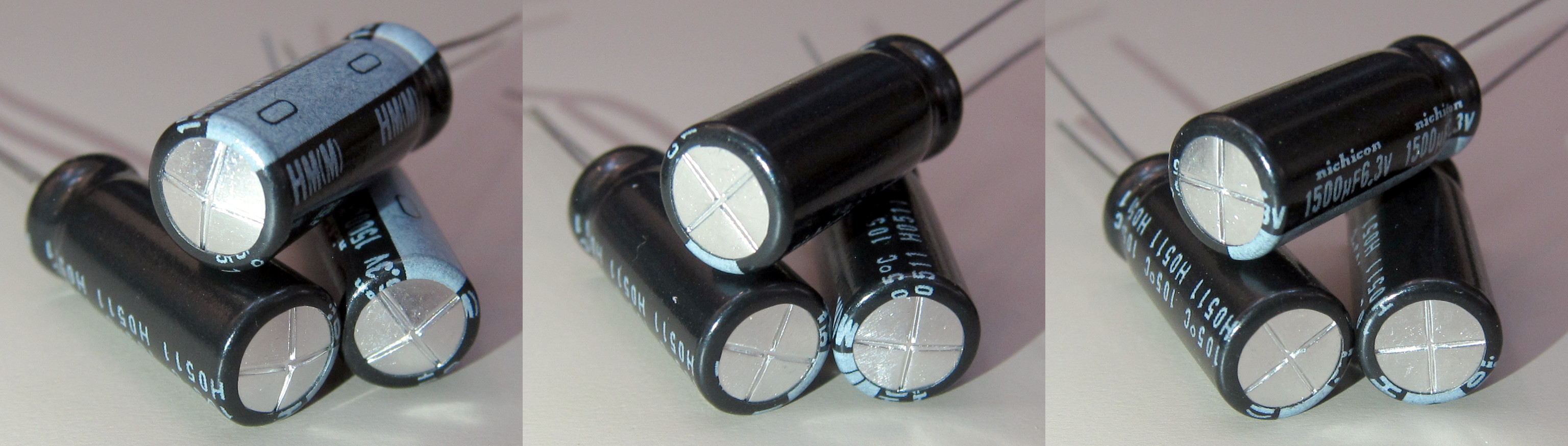
Nichicon HM capacitors sorted by bloating.
Left: Bloated. Middle: Slightly bloated. Right: Not bloated.
Open-circuit voltage
When a capacitor is left unused for many years, the expectation is that it will not be charged and have zero open-circuit voltage.
An interesting observation is that these Nichicon HM capacitors will charge themselves with tens to hundreds of millivolts, even after being discharged/shorted for a long time. Even more strangely, all of them self-charged with a negative voltage (the positive terminal of the capacitor became more negative than the negative terminal), so this is not the usual dielectric absorption that would cause the capacitor to self-charge with a positive polarity if it had been recently charged and discharged.
The following chart plots S-curves that show the distribution of the open-circuit voltage for the three bloatedness groups. Two other capacitor models were used as control groups for comparison. All capacitors have never been used.
The chart plots the open-circuit voltage measured for every capacitor in each group, sorted by voltage within the group. Each data point is one capacitor. An S-curve chart makes it easy to see the median value, how many outliers there are, and how much they vary from the median. The number of data points for each series varies depending on how many capacitors are in each group (I have more Nichicon HM capacitors than the other types).

Open-circuit voltage for the three groups of Nichicon HM, and two other capacitor models for comparison
This plot includes these capacitors:
- 169 Nichicon HM capacitors, sorted into bloated (104), slightly bloated (12), and not bloated (53) groups
- Two models as control: Nichicon HZ (18), and Kemet 759 (10)
The median Nichicon HM capacitor had -262 mV, -186 mV, and -65 mV of open-circuit voltage in the bloated, slightly bloated, and not bloated groups, respectively. The big differences in the open-circuit voltage that correlate with the bloatedness of the capacitor suggest that this open-circuit voltage is related to the bloating.
Compared to the failing HM capacitors, both of the other models have very low voltage (about 1000x lower, at +0.1 to +0.3 mV), and have positive polarity. The positive polarity and small magnitude might be explained by a small residual amount of dielectric absorption.
An electrolytic capacitor consists of an anode (with thin oxide dielectric), a cathode, and electrolyte. A battery has a similar construction, except without the dielectric and different materials for the two electrodes. The presense of a voltage on the capacitor makes me suspect that the electrolyte reacts with the anode/cathode and has dissolved enough of the oxide to turn the capacitor into a weak battery, which leads to corrosion of the anode/cathode, the production of gas, and the generation of a voltage.
Perhaps a capacitor’s open-circuit voltage could be an early predictor for whether the capacitor will fail by corrosion, where a capacitor that charges itself is a sign of an electrochemical reaction that leads to corrosion. Even the non-bloated HM series capacitors had significant negative voltage, while the other two models all had much smaller positive voltages. Futher measurements of other capacitor models and measurements on new capacitors before corrosion begins (which is difficult to do because nobody knowingly makes corroding capacitors and advertises that fact) will be necessary to see whether self-charging is a useful indicator of corrosion on other capacitor models, and whether it shows up early enough in a bad capacitor’s life to detect corrosion in new capacitors (perhaps with high-temperature baking) before the more obvious symptoms show up.
Charging up the capacitors: Reforming
 Aluminum electrolytic capacitors in storage are known to have increased leakage current due to thinning of the dielectric layer, which can be reversed by reforming. Nichicon’s application guidelines recommend charging the capacitor to its rated voltage through a resistance of 1 kΩ for 30 minutes if the capacitor has been stored for more than two years [3]. Perhaps reforming could repair even a serious case of corroded dielectric?
The next chart plots the charging current over time when I tried charging the capacitor using 5V through a 1 kΩ resistor (note the logarithmic time scale). Because the capacitor is charging using 5V through a 1 kΩ resistor, the charge current is limited to at most 5 mA when the capacitor voltage is zero. Charging through a resistor also means the capacitor voltage is not constant, but slowly rises as the charge current decreases.

Charging with 5V through a 1kΩ resistor. All of the Nichicon HM capacitors leak current abnormally, but the bloated ones leak more. Plotted for comparison is an ideal 1500µF capacitor and a measurement of a new Kemet 1500µF capacitor.
I tested 10 samples, five each from the bloated (red) and non-bloated (blue) groups. The chart shows a clear difference between the bloated and non-bloated samples, with non-bloated samples having lower leakage current that decreases more quickly. It seems that more corrosion causes more swelling and more leakage current, and the non-bloated capacitors are in better condition.
But this is far from saying that the non-bloated capacitors are behaving normally. The datasheet says leakage current should be less than 0.03CV within two minutes, which is 0.225 mA for 1500µF at 5V. The test sample that reached this value quickest took almost 8 hours, and the longest one took more than 14 hours.
For comparison, the theoretical charging curve of an ideal 1500µF capacitor and a measurement of a Kemet 759 1500µF capacitor are plotted (black). The measurement of the good capacitor agrees fairly well with theory. It is obvious that the non-bloated bad capacitors are far from normal.
Even worse than abnormal leakage currents, all of the non-bloated capacitors swelled while being charged, and at least several ruptured. Here is a time lapse of non-bloated sample 5, which began to swell visibly at half an hour, and ruptured at 2.5 hours. Even the capacitors that look normal are still unusable.
Time lapse video of 8.5 hours while charging non-bloated sample 5 with 5V through a 1kΩ resistor. Swelling starts at half an hour, rupturing at 2.5 hours.
Post-reforming measurements
| Bloated | Not bloated | ||||
|---|---|---|---|---|---|
| µF | mV | µF | mV | ||
| Sample 1 | OL | -239 | 3171 | -163 | |
| Sample 2 | OL | -306 | 3392 | -5 | |
| Sample 3 | OL | -529 | 3531 | -22 | |
| Sample 4 | OL | -519 | 3517 | -8 | |
| Sample 5 | OL | -450 | 3224 | -23 | |
Capacitance
Charging up the capacitors for a day reduced their leakage to reasonable levels, which would allow capacitance to be measured. The capacitors were measured after sitting for a few days after charging. All of the bloated capacitors had already developed leakage currents high enough that their capacitance couldn’t be measured by my multimeter. The non-bloated ones seemed to retain the low leakage state longer, but measured over twice their 1500µF rated capacitance. The high capacitance measurement is probably due to the dielectric layer being too thin, or that corrosion had roughened and increased the surface area of the anode aluminum foil.
Open-circuit voltage
The magnitude of the open-circuit voltage of the bloated capacitors increased after being charged for a day (none exceeded -500 mV before reforming, but two exceed it after), while it decreased for most of the non-bloated capacitors. I can imagine that reforming the insulating oxide layer could slow down corrosion by protecting the aluminum foil, but it seems to have made corrosion even worse for the capacitors that already started out worse.
The fact that charging the capacitors reduced the negative open-circuit voltage (a proxy for corrosion rate?) suggests that these capacitors may have survived longer had they been in use (kept charged) rather than stored.
Conclusions
When electrolytic capacitors swell, it is not necessarily due to heat, ripple current, or power-on time. The low-ESR Nichicon HM capacitors appear to be internally corroding even in room-temperature storage. Within the same batch, there is variation in how much corrosion and swelling has occurred, and the amount of swelling seems related to how much the capacitor has deteriorated (as measured by leakage current). However, even capacitors with no visible swelling are clearly unsafe to use. If they are charged to their normal operating voltage, they will have high leakage currents (possibly enough to damage other parts of the circuit), swell, and leak, even if charged slowly.
There have been various claims about the Nichicon HM failures that distance it from the rest of the capacitor plague, including the claim that the cause of failure was “overfilling” the electrolyte. My measurements here suggest that the failure mechanism is the same as the rest of the capacitor plague: Aluminum anode and cathode foils corroding in electrolyte, high capacitance, high leakage current, self-charging, gas generation, and eventual rupture. Further measurements will be necessary to see whether self-charging voltage could be used to detect corrosion before swelling begins.
It’s time to replace the capacitors on my 23-year old motherboard a second time, this time with solid polymer capacitors.
Leave a Reply