The Sparkle Power SPI270LE Flex ATX power supply has a rather noisy 40 mm fan that that is temperature-controlled to reduce noise when cool. The fan control circuit failed and powered the fan at full speed regardless of temperature. After much work, it is repaired.
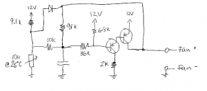
Power supplies usually use single-layer circuit boards, making reverse-engineering the circuit possible. It is interesting the power supply uses entirely discrete devices using two bipolar PNP transistors to implement fan speed control.

A TTC103 negative temperature coefficient thermistor is used (10k at 25°C, 2.5k at 60°C, 1k at 85°C). The circuit appears to use both the output voltage as negative feedback and the thermistor voltage to set the output current that controls fan speed. The diode is probably used to ensure the fan spins even at low temperatures.
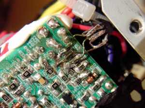
The first (left) PNP transistor failed, and leaked current from the base to collector. This caused enough emitter-base current to turn on the fan even when the base voltage is high. The failed transistor was replaced with a TO-92 PNP transistor (BC327). Surface mount components are hard to solder…
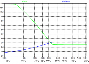
Being curious how the fan speed control circuit really behaves, I simulated it using LTspice. The fan is modeled as a 100 ohm resistance. Output voltage and the thermistor voltage are plotted against thermistor resistance. Thermistor resistance is non-linear (roughly 10k at 25°C, 1k at 85°C). The temperature at which the fan speeds up can be adjusted using the 6.8k/36k divider and is strongly dependent on the forward base-emitter voltage of the transistors. Two BC327 transistors are simulated because I can’t read the marking on the transistor. The circuit creates a nice speed vs. temperature curve, with a reasonably linear transition region (55°C-95°C) and still keeping the fans on (27 mA) at low temperatures.

