So this post is almost four years late…
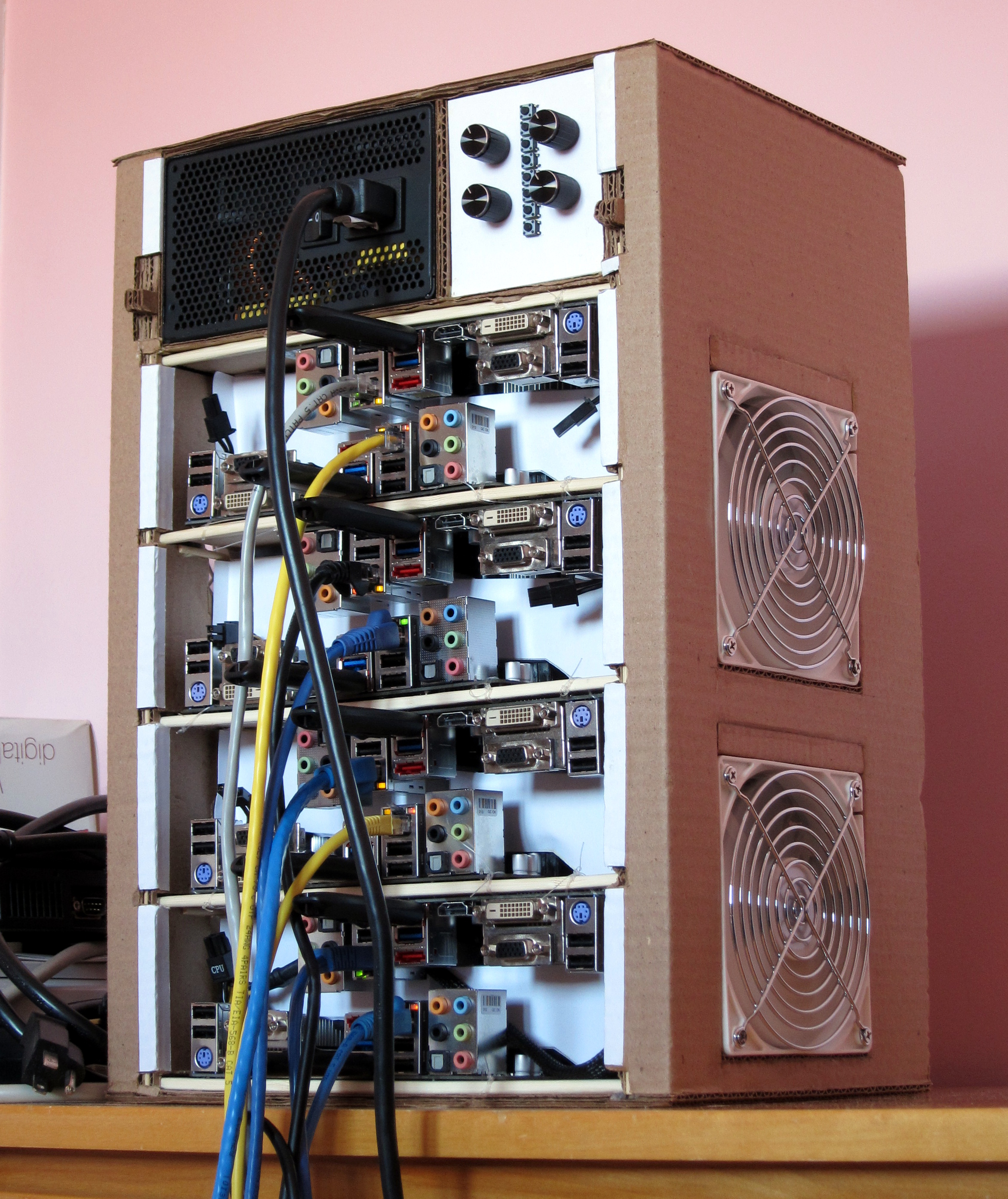
This post is about a cardboard computer I built in 2015. It served as half of my simulation cluster during the latter half of my Ph.D. work. This is a continuation of a series of cardboard computer cases I’ve built (2014/2012, 2010). Compared to the previous boxes, this one packs even more systems (8) into a box, while still sharing one power supply.
![]()
| box11-box18 | ||
|---|---|---|
| Processors | Core i5/i7 4670K-4790K, around 3.9-4.3 GHz | |
| Motherboard | ASRock H81M-ITX | |
| Power Supply | Cougar GX 1050W (80 PLUS Gold) | |
| Disks | Sandisk Extreme USB 16 GB | |
| Cooling | 8×Modified Intel Boxed Heatsink-Fan, 4×Silverstone FM121 | |
| Volume | 26.8 L (3.35 L/system) | |
| Weight | 10 kg | |
| Max Power (wall) | ~1100 W | |
| Completed | February 2015 | |
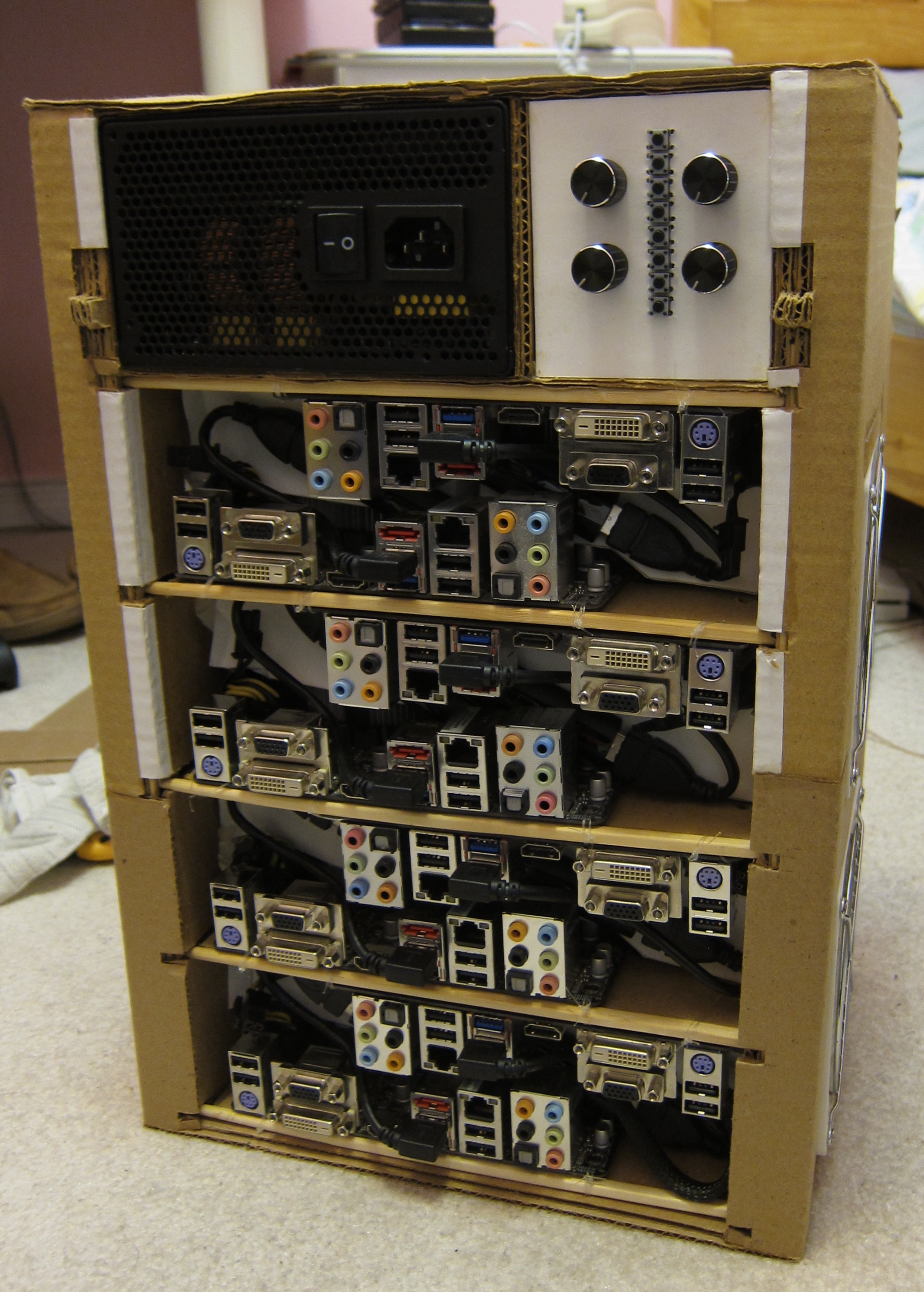
Computer
This box holds eight quad-core Haswell (Intel 4th generation Core) systems using Mini-ITX motherboards. My design goal was to pack CPU performance into a small space, at low cost. Since the intended use was to run CPU microarchitecture simulations (for my Ph.D. work), I cared only about CPU performance. My workload did not require large amounts of DRAM. The GPU is not used. Disks are used only to boot up Linux. Storage is accessed over the network using NFS.
The total cost was about $4,500 CAD for all 8 systems.
Memory
Many consumer DIMMs come with (useless, decorative-only) heat spreaders. I had to remove all of them because the heat spreaders were too tall. Unfortunately, one stick (Patriot Viper 3) used unusually strong double-sided tape to stick on the heat spreader, and I ripped off one DRAM chip from the DIMM. Oops. Always use a solvent (e.g., lacquer thinner) to weaken the tape first, and pry slowly…
Disks
There are no drive bays. I use SanDisk Extreme USB drives as the only disk. I used a short extension cable so the USB drive can be mostly hidden instead of sticking straight out.
Buttons
There are 8 power buttons, located near the four fan speed control knobs.
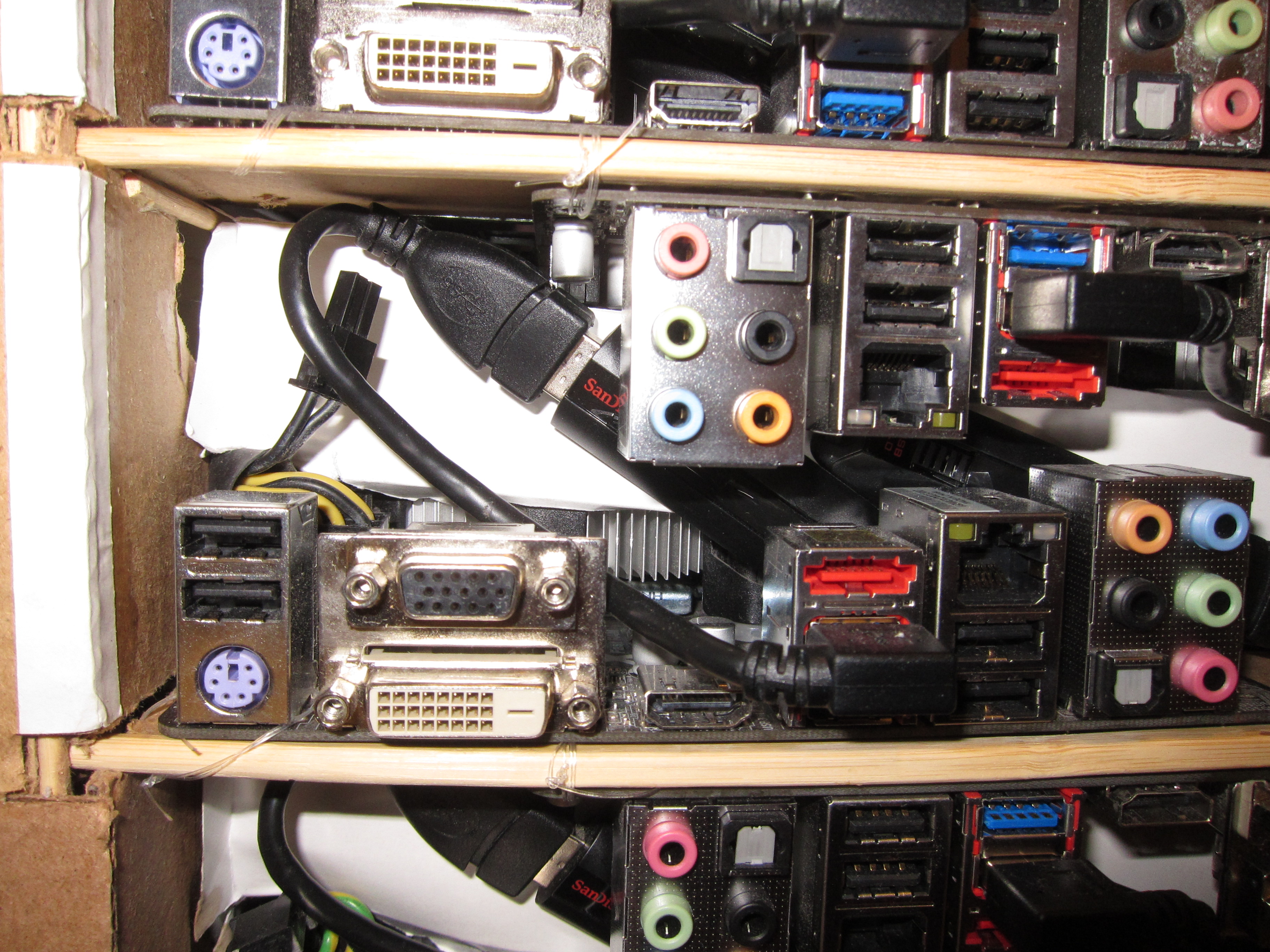
The USB drive is connected using a short USB 3 extension cable
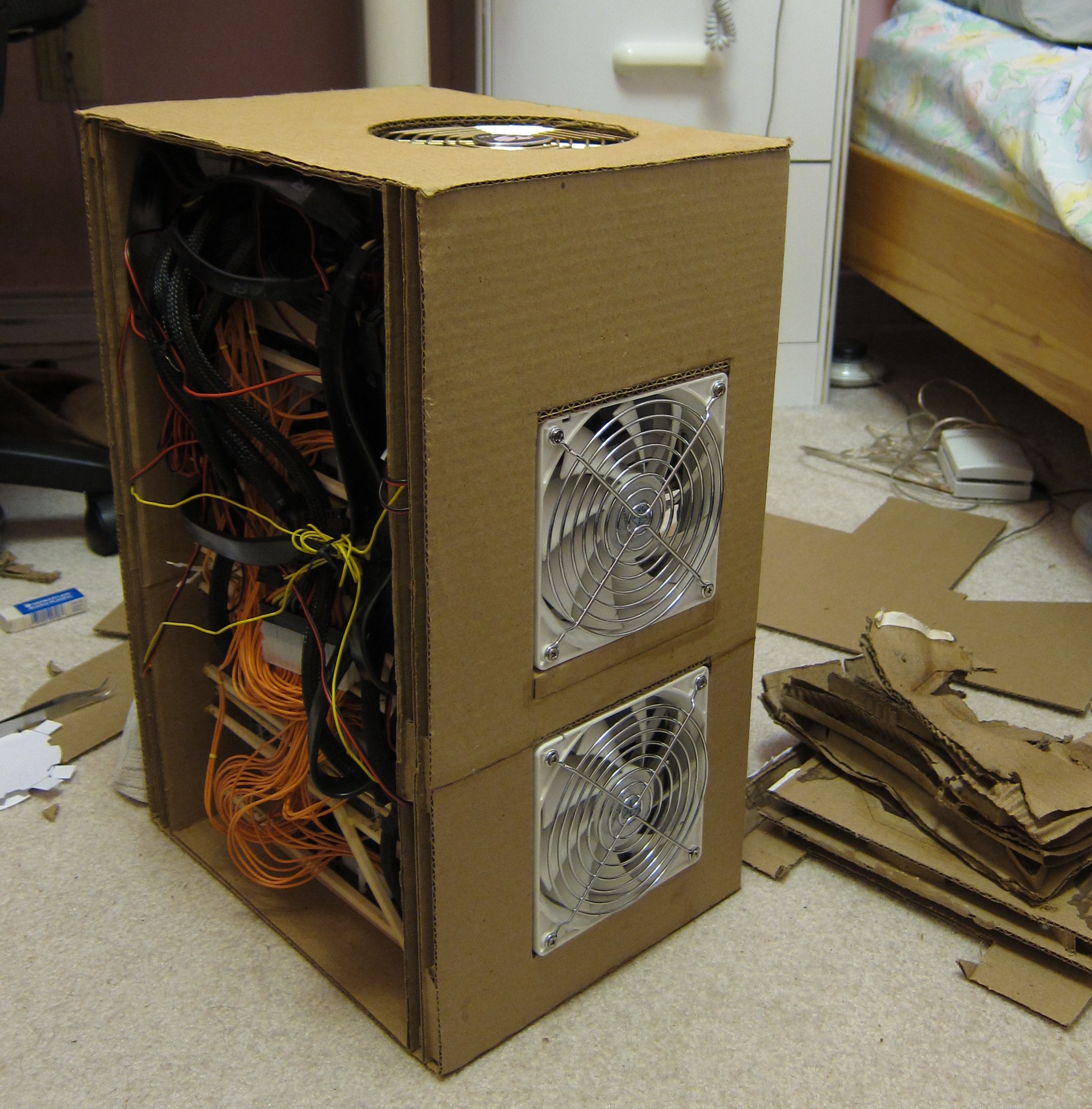
Cooling
The eight processors are cooled using the heatsink-fans that comes with the retail box processors. These heatsink-fans are small, reasonably quiet, and provide (barely) adequate cooling. When trying to pack many computers into a small space, small size is important. It’s hard to find anything significantly better at a similar size. I made a simple modification (short the ambient temperature thermistor) to increase the fan speed at the expense of higher noise.
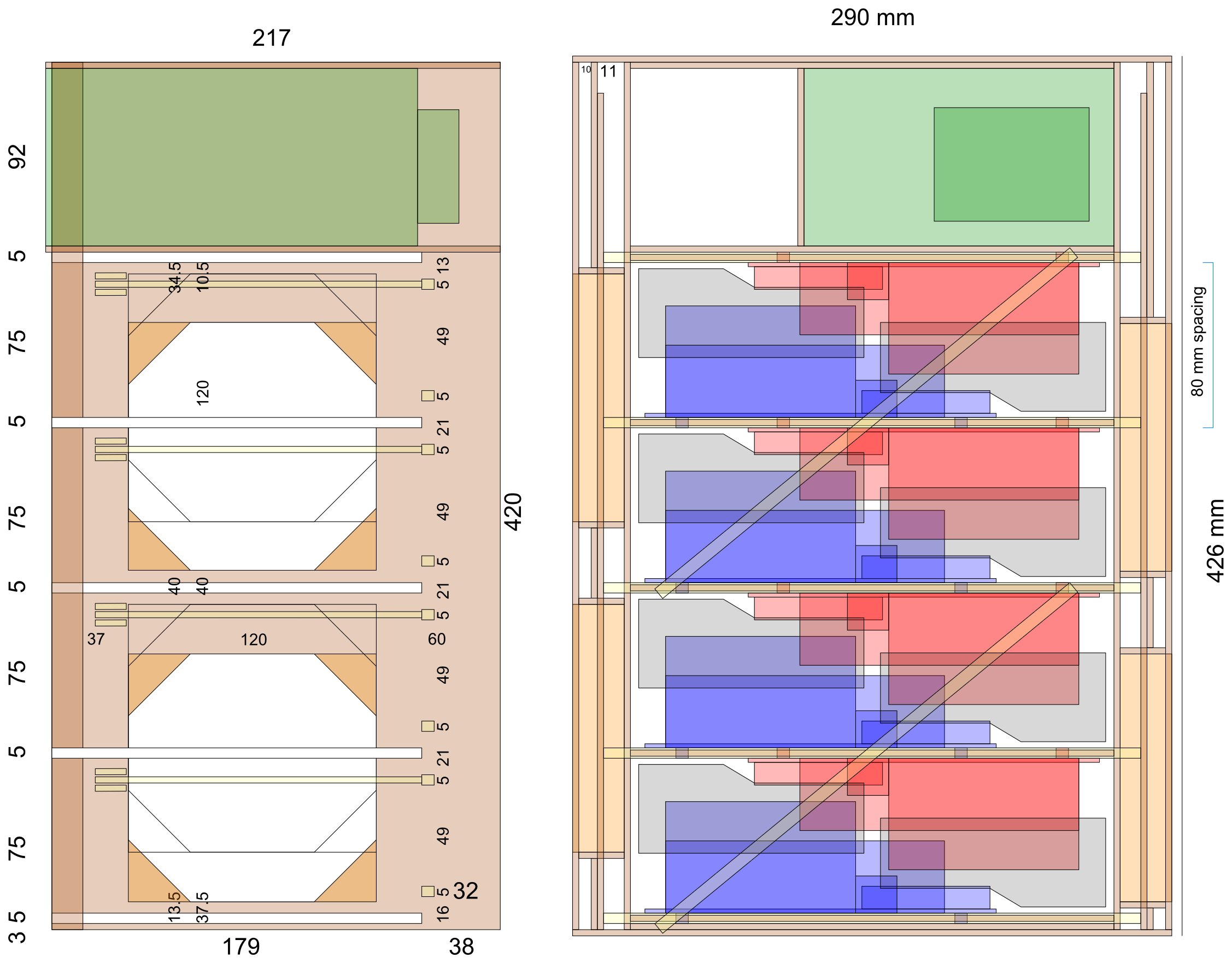
I also used four 120 mm case fans. The case fans ingest cool air from the side and blows this air directly into the intake of the CPU fans, so the CPU fans do not recirculate hot air trapped in the tightly-packed case. Each CPU fan has a fan shroud that directs the air from the case fans into the CPU fans. The hot exhaust from the CPU fans leaves through the front of the case. I chose Silverstone FM121 fans (110 CFM) for their high airflow, but I did not need to run them at full speed (Four of them at full speed is annoyingly loud). Choosing case fans was not easy, as most 120 mm fans are optimized for “quiet” and don’t produce enough airflow.
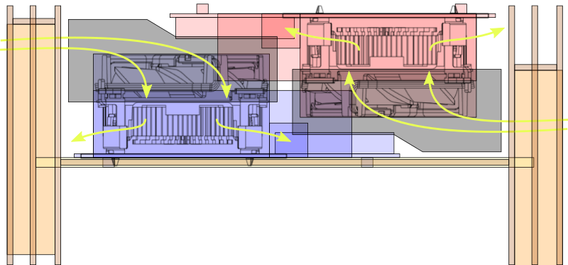
Airflow: Cool air enters the side through the 120 mm case fans, is blown through the CPU fans, then exits out the front of the computer.
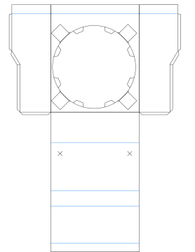
The fan shroud is made from one sheet of letter-sized card stock
CPU Fan Speed Modification
The Intel stock fans are controlled by PWM (4-pin connector). But the speed is also controlled by a thermistor hidden in the fan, so the fan speed at a “100%” PWM signal actually depends on the ambient temperature. Since I wanted higher-performance CPU fans (even at the expense of noise), I shorted out the thermistor with a dab of silver conductive paint to increase the fan’s maximum speed (behaving as though the ambient temperature were high). This only increases the maximum speed of the fan and does not disable PWM, so the CPU fans remain inaudible when the CPU is cool and idle.
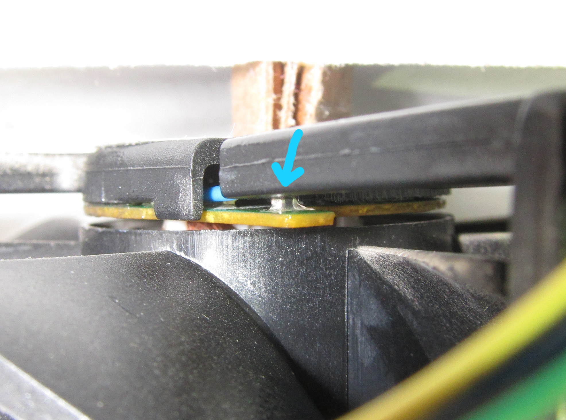
Shorting out this thermistor with conductive paint causes the fan’s maximum speed to increase.
With this modification, the Intel boxed heatsink and fan is just barely sufficient (about 100°C max) for a slightly-overclocked quad-core at full load when packed into this box.
Electrical
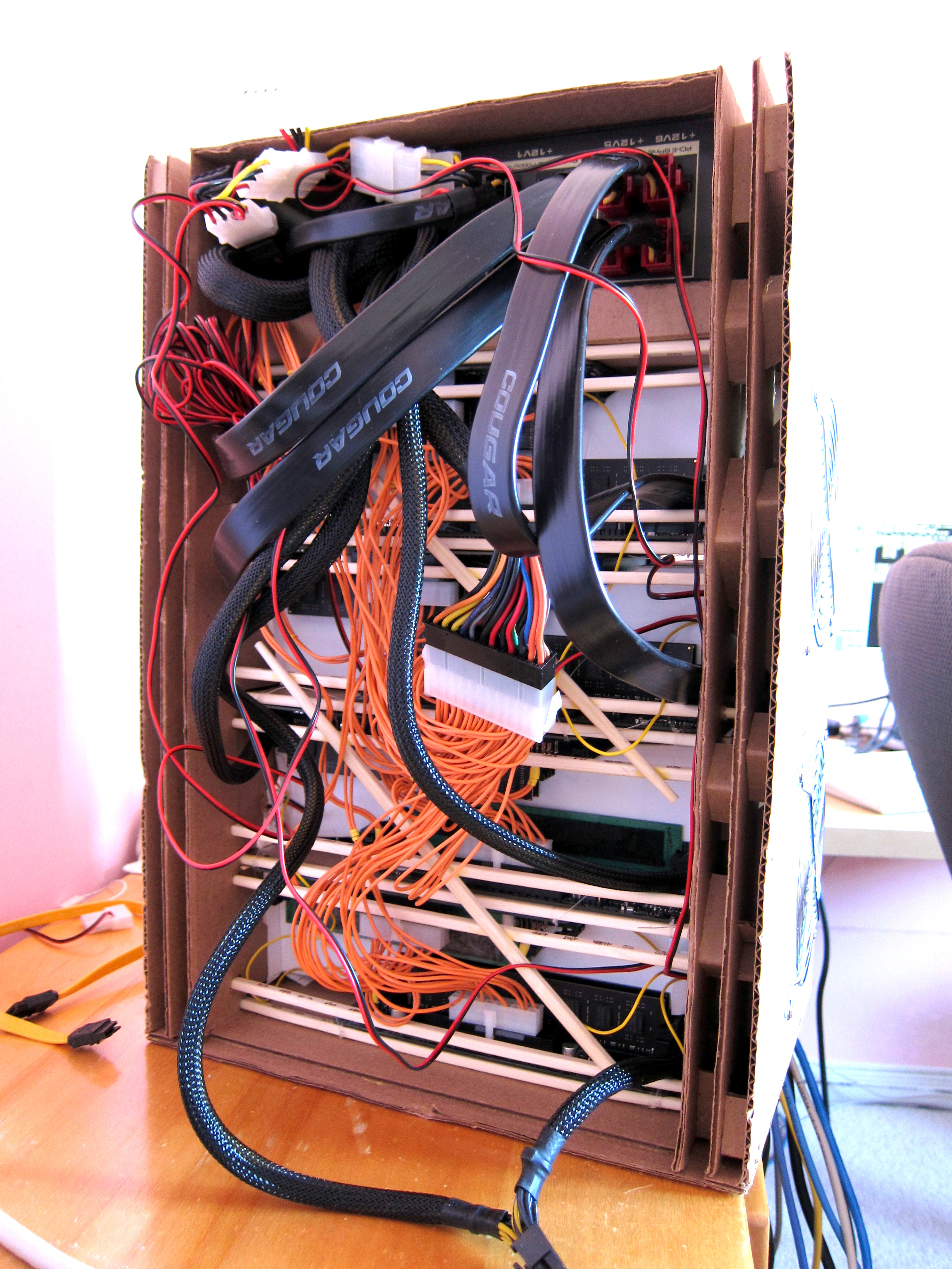
Power Supply Sharing
Unlike previous systems, I decided to build the power supply splitter cable from scratch, using connectors, wire, and crimp pins. This gives better control over the exact length of each segment of the cable, allows me to omit some wires (saves space when using an 8-way splitter), and saves time compared to modifying existing a bunch of two-way splitters. I used one 24-pin ATX male connector and eight 20-pin ATX female connectors. The PS_ON pin (Pin 16) of every system was connected together. PS_ON is an open-drain pin (pulled low when a motherboard wants power on, left floating otherwise), so the net effect is that the power supply is on whenever any motherboard wants to be on.
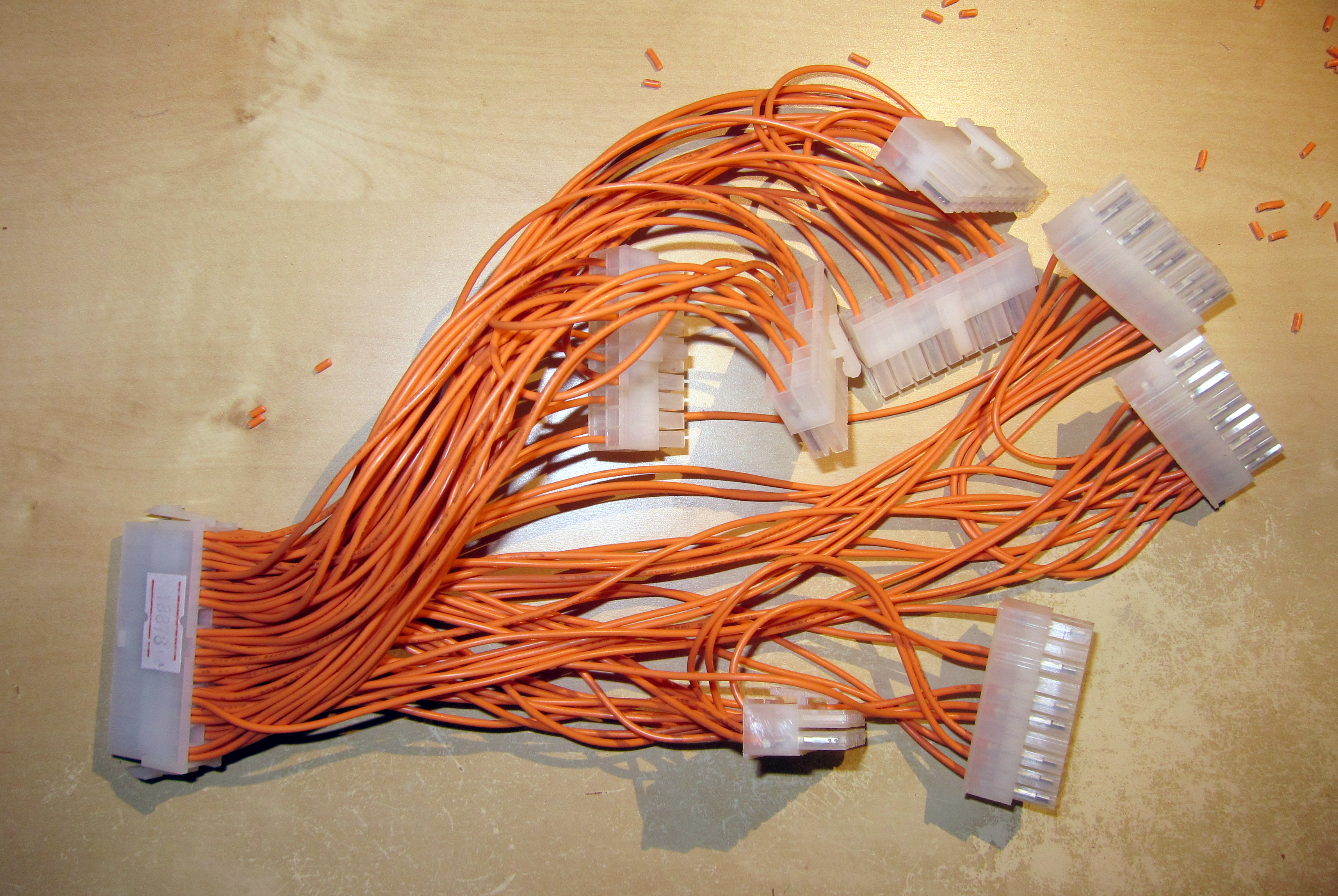
Eight-way ATX power splitter.

The ATX splitter was built with a crimp tool, wire, crimp pins, and connectors.
Most of the 12V CPU power connectors are made from modified PCIe power connectors. The 6-pin PCIe plugs will fit into a 4-pin 12V CPU power connector on a motherboard, but with inverted wiring. I popped out the pins on the connector and flipped them, then used PCIe connectors to power some of the motherboards. (Do not plug it in a GPU now!)
Mechanical
It may appear as though you could slide out each pair of machines independently. Not even close. First, there are power cables. Second, the systems are packed so tightly that they actually interlock. Assembly is quite difficult, because it involves first stacking all of the machines on a flat surface without the box, connecting the power cables, then lowering the box over the stack of machines.

The stack of computers actually interlock, so they cannot be individually removed.
Some of my previous cardboard systems used rails to hold the motherboards, which slide in from the front of the case. This one uses trays, where the motherboards are first attached to the trays before being assembled into the case. Motherboard trays are better than rails. Rails were extremely labour-intensive to build, did not work well (motherboards occasionally fall out because the box isn’t entirely rigid), and did not add any value (motherboards could not be easily removed anyway).
Things I’d change next time
Add a few more millimeters between each computer. Currently, the PCIe slot from one motherboard is less than 1cm from the CPU fan of the next one, and the gap changes when the motherboards flex. I needed to insert cardboard spacers to keep them apart. This puts pressure onto the CPU fans, and it is occasionally enough pressure to push the CPU fan to contact the CPU heatsink.
Oops: Cardboard doesn’t like water
Cardboard is easily damaged by water. In April 2018, this computer was stored on the floor of the basement, and the basement floor leaked water from melting snow and rain. The computer absorbed the water from the wet carpet… and melted. I didn’t discover this until a day or two later. By then, one motherboard was damaged (one capacitor rusted off, causing the loss of one DRAM channel), but surprisingly, there doesn’t seem to have been other damage. The damaged (and moldy) portion of the case was cut off and rebuilt.
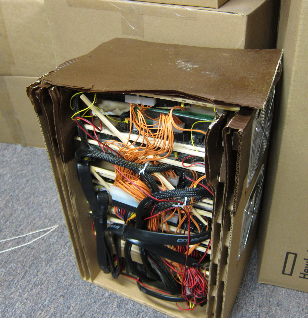
Melted computer, flipped upside-down. The bottom third of the computer (top in the photo) melted, with some mold growth
Front: The damaged portion was removed and rebuilt.
Rear: The damaged portion was removed and rebuilt.
Leave a Reply