Per-Drive Results
- Seagate ST-157A 45 MB
- Maxtor 7405AV 405 MB
- Seagate Medalist ST 1.28 GB
- Seagate Medalist Pro 9.1 GB
- Samsung SV0432D 4.3 GB
- Seagate ST1 5 GB
- Toshiba MK8034GSX 80 GB
- Hitachi Deskstar 7K80 82 GB
- Western Digital Caviar SE16 250 GB
- Seagate Barracuda 7200.9 160 GB
- Seagate Barracuda 7200.11 320 GB
- Western Digital S25 300 GB
- Seagate Cheetah 15K.7 450 GB
- Samsung SpinPoint F3 1 TB
- Hitachi 7K1000.C 1 TB
- Toshiba P300 3 TB
- Toshiba X300 5 TB
Seagate ST-157A
| Seagate ST157A | |
|---|---|
| Capacity | 44.7 MB |
| RPM | 3602 |
| Sectors (512B) | 87360 |
| Sectors per track | 26 |
| Tracks | 3360 |
| Surfaces | 6 |
| Skew (°, rev) | 0 |
| Max. seek (ms) | 63.0 |
| Random access (ms) | 39.7 |
| Random seek (ms) | 31.3 |
| Avg. track pitch (TPI) | 0.65k |
| Avg. OD linear density (kbpi) | 10 |
| Track layout |  or or  |

Bottom

Top
The ST-157A is a 44.7 MB hard drive that was likely released in 1989. The one I have seems to be manufactured in 1990, but the earliest reference to the model I have found is in an advertisement from 1989.
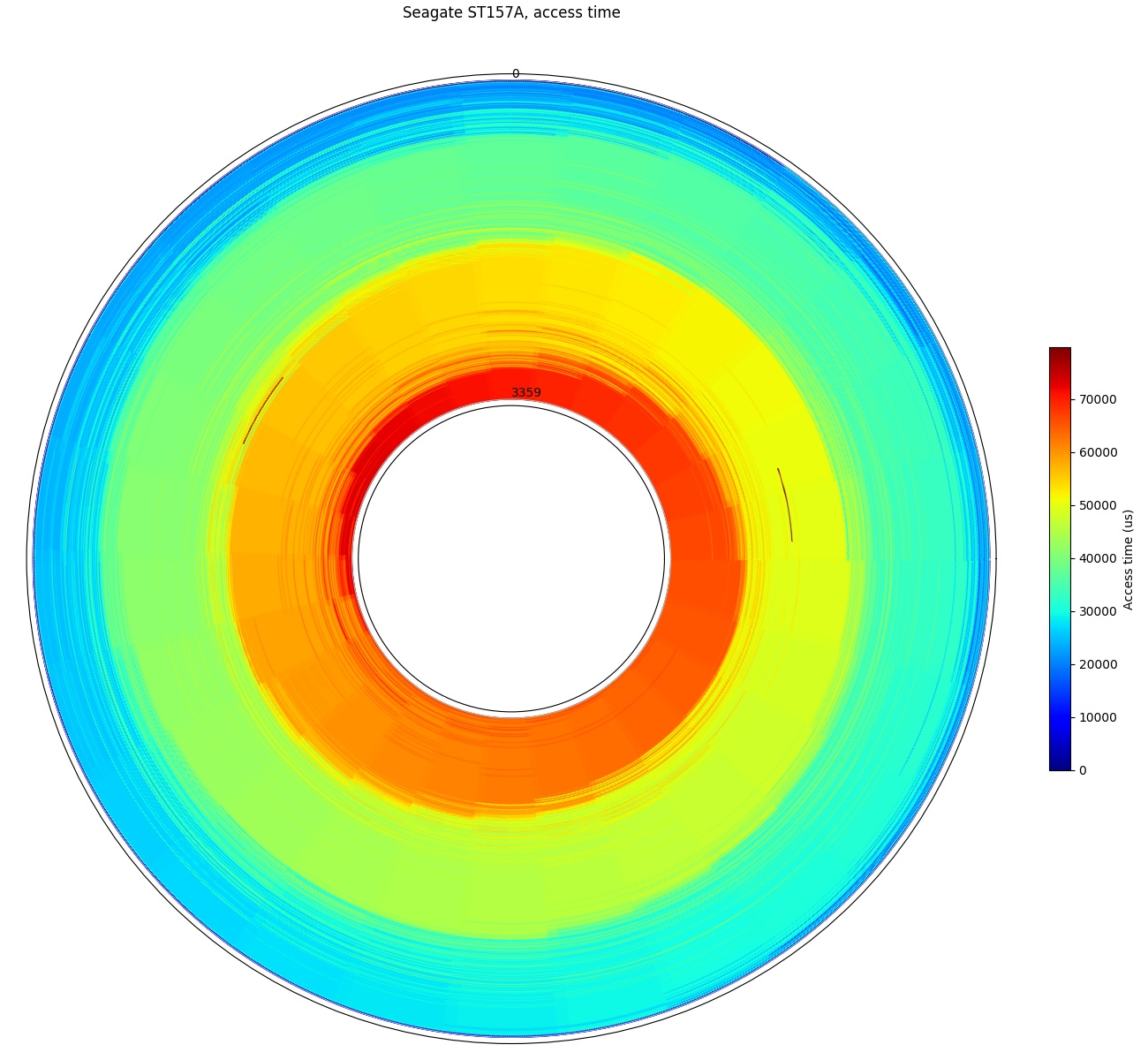
Full-disk access time: The slow stepper motor actuator takes 4.6 revolutions (at 3602 RPM) to reach the furthest sector.
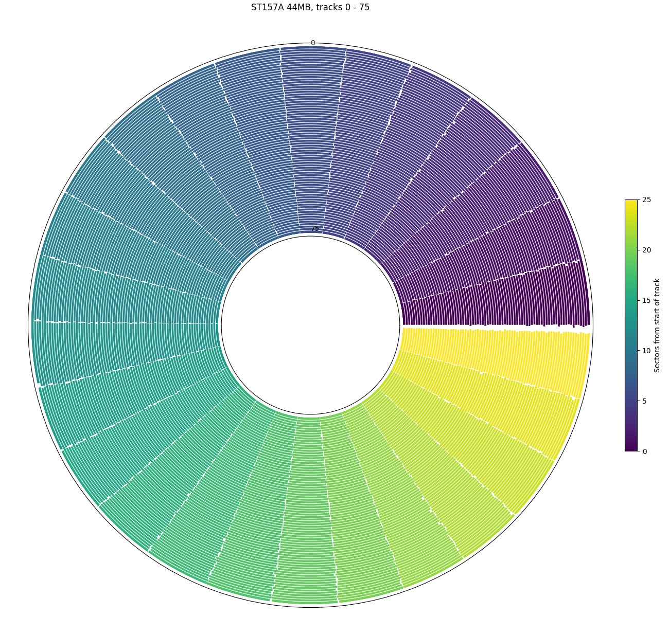
Angular position, first 76 tracks: There are 26 sectors per track and no skew
The ST-157A uses a stepper motor actuator, rather than the more modern voice coil. It has slow seek times compared to voice coil drives, and is slow even relative to a rotation speed of 3600 RPM. It takes about 3.6 revolutions (60 ms) to do a full-stroke seek (from outside to inside track), which makes the full-disk access time plot look somewhat unusual for having four bands of colour.
The ST-157A has no track skew. As seen in the angular position plot, the starting sector of every track starts at the same angular position. It also does not use zoned bit recording, so the entire disk has 26 sectors per track. There appears to be a slightly bigger gap between sector 25 and 0 of each track.
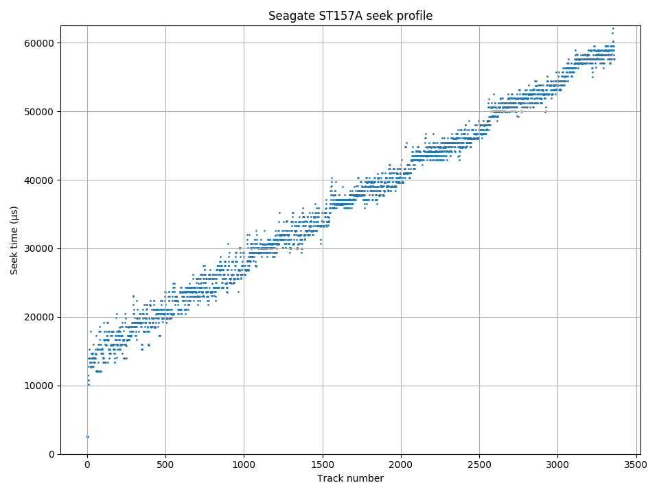
Seek profile: The shape of the seek profile is unusual. There is a large >10 ms delay even for a single-track seek, and then seek times increase linearly with track number.
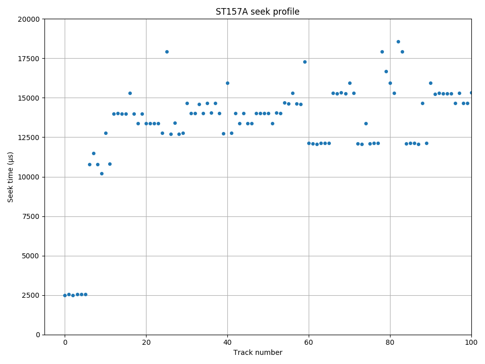
Seek profile, first 100 tracks. First 6 tracks are on the same cylinder and do not require a seek.
The ST-157A’s stepper motor actuator has an unusual seek time plot. It is unusually linear with distance, after an initial 11 ms delay for a single-track seek. This seems to suggest that the head travels at the same speed through (almost?) the entire stroke, without significant acceleration and deceleration phases. I do not know if this is characteristic of other stepper motor actuators, as I have not tested any other stepper motor-based drives.
One interesting fact to consider is the stepper motor’s step rate. This drive has 560 cylinders, and it takes about 48 ms to travel about 558 of those tracks, which leads to a step rate of about 11.6 kHz. I’m not particularly familiar with stepper motors, but this seems surprisingly fast. Even if we ignored the problem with head positioning precision, the step rate required for reasonable seek times on a disk with more tracks would make stepper motors impractical. For example, a full-stroke seek on the 5 TB Toshiba X300 (about 328k tracks) takes 14.6 ms, which is an average speed of about 22 million tracks per second (peak speed is probably closer to 39 Mtracks/sec).
Zooming in to the first 100 tracks of the the seek time plot, we can see that the first 6 tracks all have the same “seek time”. This confirms that the drive has 6 recording surfaces and that it uses one of the head-first track layouts. The first 6 tracks (one on each surface) does not require moving the disk head. I know of no way to distinguish between the traditional (type F) and cylinder serpentine (type A) layouts by performance measurements alone on this drive.
Maxtor 7405AV, 405 MB
| Maxtor 7405AV | |
|---|---|
| Capacity | 405 MB |
| RPM | 3548 |
| Sectors (512B) | 791265 |
| Sectors per track | 123 – 66 |
| Tracks | 7998 |
| Surfaces | 3 |
| Skew (°, rev) | 93° – 100° |
| Max. seek (ms) | 30.5 |
| Random access (ms) | 25.4 |
| Random seek (ms) | 16.4 |
| Avg. track pitch (TPI) | 2.4k |
| Avg. OD linear density (kbpi) | 48 |
| Track layout |  or or  |
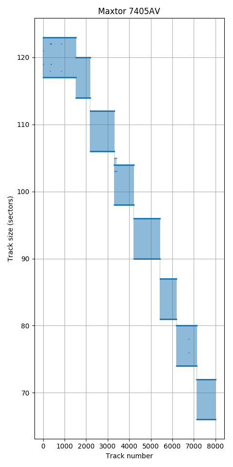
Track size: 123 to 66 sectors per track. Every 3 tracks has 6 fewer sectors.
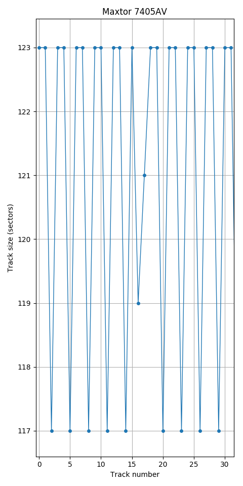
Track size, first 30 tracks: Every 3 tracks has 6 fewer sectors. These are probably used for spare sectors.
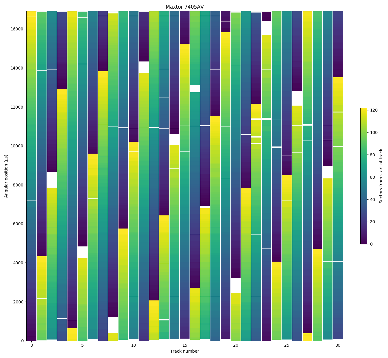
Angular position of each sector, first 30 tracks: There is a 6-sector gap at the end of every third track, probably used as spare sectors. Track 16 appears to have 4 defective sectors that were replaced using 4 sectors from the spares at the end of track 17.
The Maxtor 7405AV is a 405 MB drive from around 1994.
The track size plot shows that this drive uses 8 zones. Unlike many drives around this age, the track size actually varies within a zone. Zooming in on the track size plot shows that every 3 tracks has 6 fewer sectors. My guess is that the 6 missing sectors are spare sectors used for defects. An example is track 16, which appears to be 4 sectors smaller than expected, while track 17 is 4 sectors bigger than expected.
An angular position plot of the first 30 tracks supports this explanation. This angular position plot is plotted on a cartesian axis (track number on the x-axis, angle on the y-axis wrapping around vertically) because it is easier to understand. There is a gap at the end of every three tracks (white space between yellow and blue), which indicates that the track is not completely used, leaving some unused sectors at the end of the track. Looking at tracks 16 and 17 where there were unusual track sizes, we see that track 16 has a gap (of defective sectors?) at around 12,900 µs (275° relative to sector 0), and that the gap at the end of track 17 (at 6900 µs) is smaller than expected. My interpretation is that that 4 of the 6 spare sectors at the end of track 17 were used to replace 4 defective sectors on track 16.
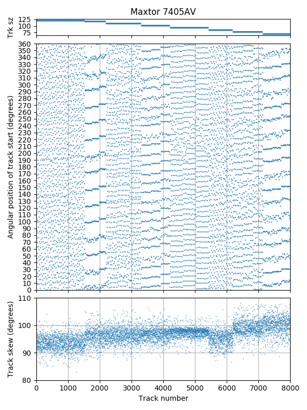
Track skew: Skew varies a little bit for each zone. Skew slowly increases from beginning to end of drive.
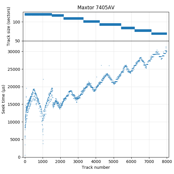
Seek profile: Seek-first track layout with 3 surfaces.
The track skew does not appear to be any particular fraction of a revolution, and differs slightly for each zone. Unusually, it appears to slowly increase toward the end of the disk.
Plotting the seek profile shows a disk that has three surfaces and uses a seek-first layout with alternating seek direction. The size of a serpentine appears to be an entire zone. I did not find a way to measure whether the surface ordering alternated or not.
With an average track density of only 2.4k TPI, the 7405AV is an unusually early example of a seek-first layout. A seek-first layout is preferred when it is faster to do an adjacent-track seek than to switch heads. At low track densities, a head switch involves less head movement than a next-track seek but this is reversed at high track density when the alignment error of tracks between surfaces is worse than the distance of a track on the same surface. The other drives I tested did not use seek-first layouts until track densities became 30 times higher (WD Caviar SE16 at 79k TPI).
Seagate Medalist ST, 1.28 GB
| Seagate Medalist ST ST51270A | |
|---|---|
| Capacity | 1.28 GB |
| RPM | 5371 |
| Sectors (512B) | 2504880 |
| Sectors per track | 145 – 76 |
| Tracks | 21599 |
| Surfaces | 4 |
| Skew (°, rev) | 129° |
| Max. seek (ms) | 22.2 |
| Random access (ms) | 18.0 |
| Random seek (ms) | 12.2 |
| Avg. track pitch (TPI) | 4.9k |
| Avg. OD linear density (kbpi) | 53 |
| Track layout | |
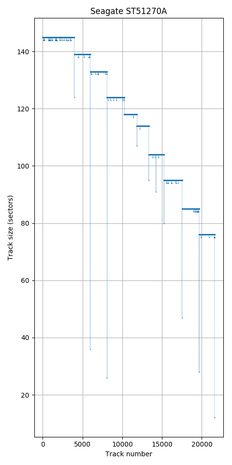
Track size: There are 10 zones
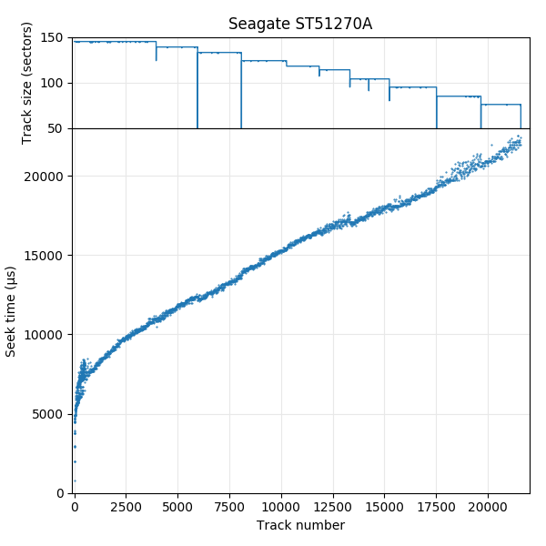
Seek profile
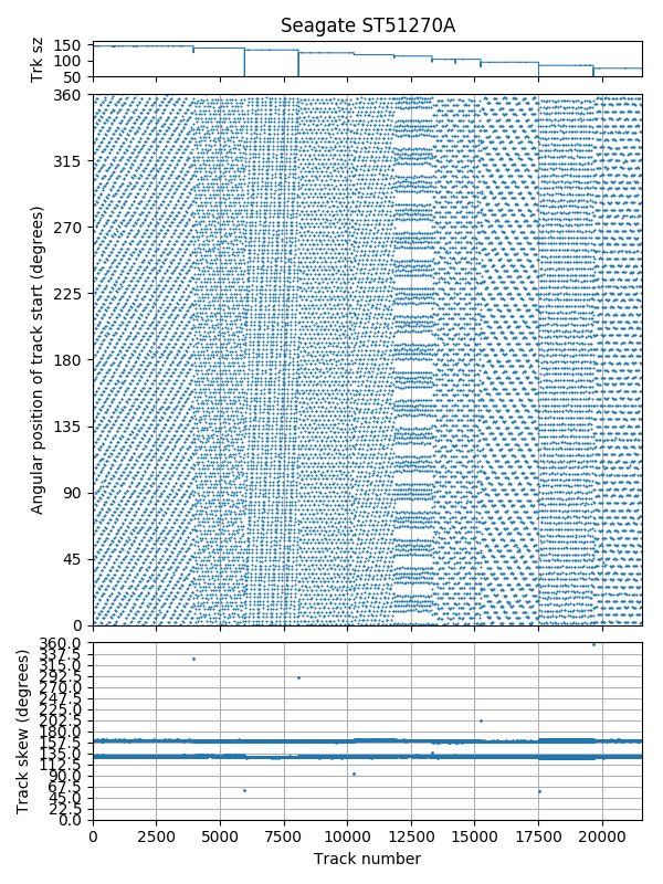
Track skew: Each zone has slightly different skew
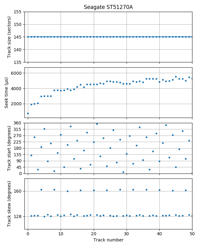
First 50 tracks: Four surfaces using a traditional head-first track layout can be seen.
The Medalist ST ST51270A is a 3.5″ drive that is an unusually thin 19 mm height (typical 3.5″ drives are 25.4 mm tall). The 5 in ST51270A indicates the thinner form factor.
The track size plot shows 10 zones, with partially-used (very small) tracks at zone boundaries, and a scattering of tracks that appear to contain sector slipping defects. The seek profile doesn’t show any sign of a seek-first (serpentine-style) track layout, and is otherwise unremarkable.
The track skew plot shows that each zone has slightly different skew, but is nearly constant across the entire disk. There seems to be two common skew values (129° and 160°). Zooming in to the first 50 tracks explains why. This drive uses a head-first track layout with four surfaces, where a cylinder switch (160° every four tracks) has a higher skew than a head switch (129°). This layout can also be seen in the seek time profile, where groups of four tracks have similar seek time (tracks 0-3, 4-7, and 8-11).
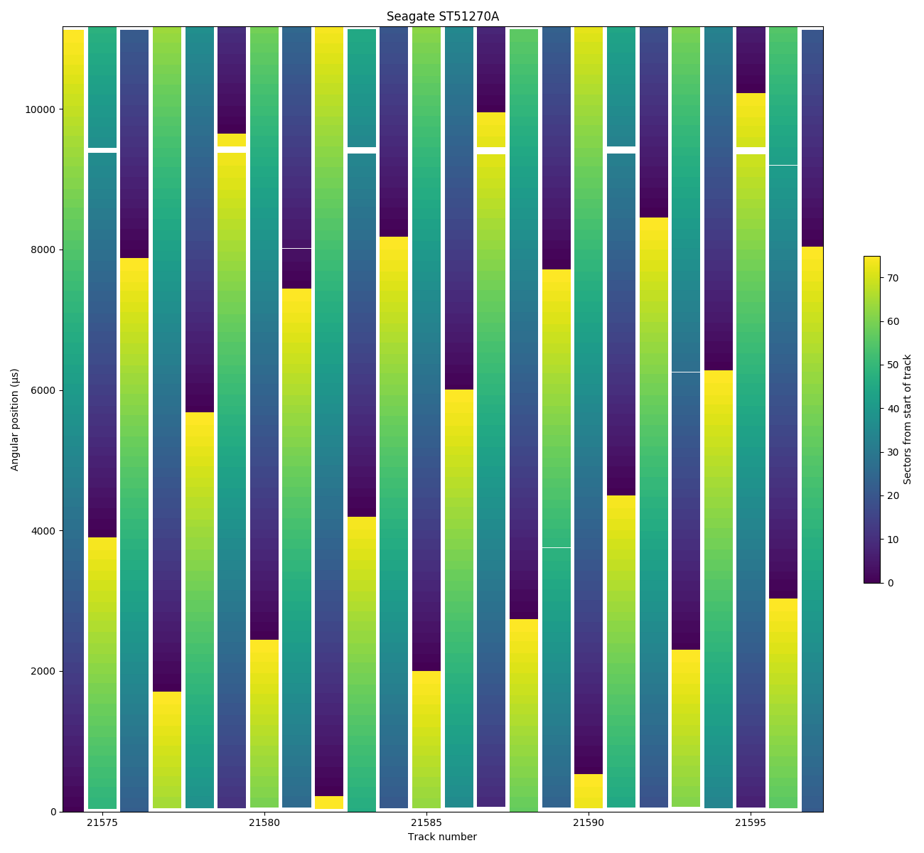
Angular position, 24 tracks near end of disk: 6 defective sectors on the same surface shows up spaced 4 logical tracks apart due to the track layout
Although it is often difficult distinguish between the two head-first track layouts, it appears this disk uses the traditional type F layout (cycles through surfaces in the same sequence) rather than cylinder serpentine type A (where the sequence reverses after visiting each surface: 0, 1, 2, 3, 3, 2, 1, 0, …). This can be seen by looking at a location with defective sectors. The angular position plot shows 24 tracks near the end of the disk (tracks 21574 to 21597) where 6 of the tracks have a one-sector defect, all of them at the same angular position (9400 µs). If I assume that defects tend to occur in groups of physically-adjacent tracks on the same surface (a single defect that spans 6 physically-adjacent tracks), the pattern of holes indicates which tracks belong to the same physical surface. These defects are spaced 4 tracks apart (and not, for example, 3, 5, 3, 5), which indicates a traditional type F layout.
Seagate Medalist Pro, 9.1 GB
| Seagate Medalist Pro ST39140A | |
|---|---|
| Capacity | 9.1 GB |
| RPM | 7209 |
| Sectors (512B) | 17803440 |
| Sectors per track | 297 – 169 |
| Tracks | 72048 |
| Surfaces | 8 |
| Skew (°, rev) | 85° and 89° alternating |
| Max. seek (ms) | 18.3 |
| Random access (ms) | 14.1 |
| Random seek (ms) | 9.7 |
| Avg. track pitch (TPI) | 8.2k |
| Avg. OD linear density (kbpi) | 100 |
| Track layout | or |
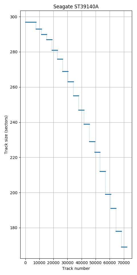
Track size: 18 zones. No sign of varying track size due to sector defects.
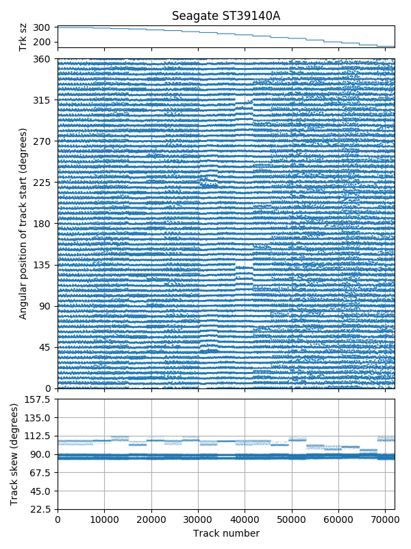
Skew: Track starts appear (but may not be) aligned to 1/64 revolution, but none of the skews are actually multiples of 1/64 revolutions.
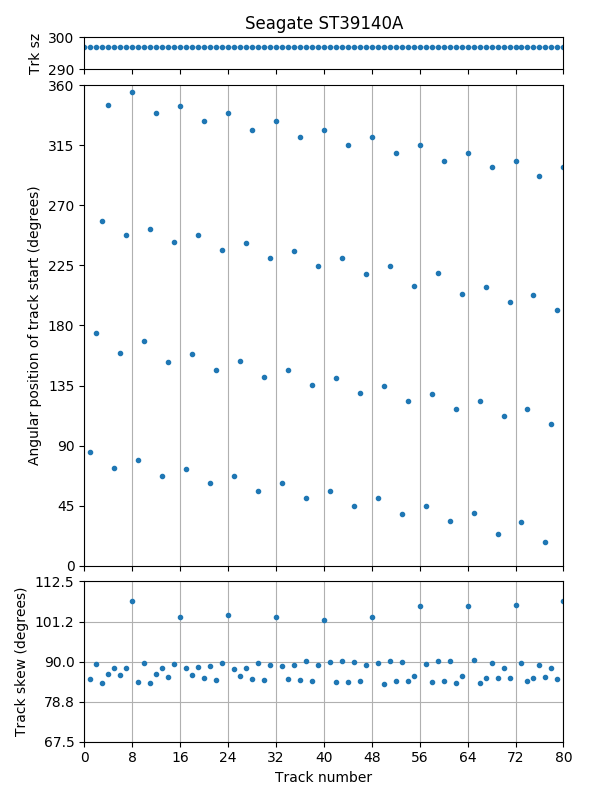
Skew, first 80 tracks. Skew is higher every 8 tracks (cylinder change)
The Seagate Medalist Pro was the first 7200 RPM IDE hard drive, released in 1998.
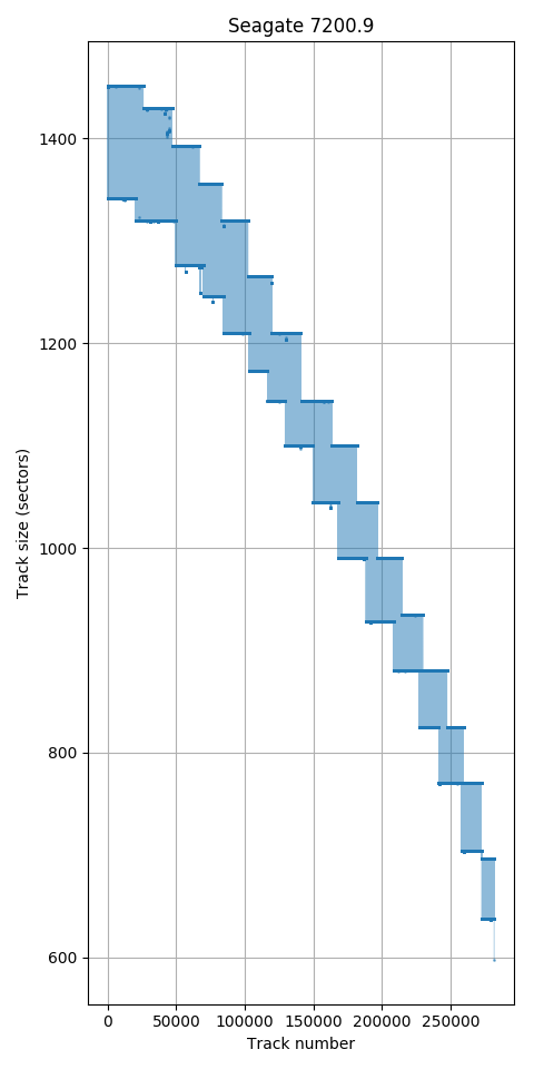
The track size plot shows 18 zones, with all tracks in a zone having the same size. This raises the question of where the defective sectors are, as there appears to be no sector slipping, nor space reserved for space sectors.
The track skew plot shows that track start positions appear to be aligned to some multiple of 1/64 of a revolution (5.625°). (The angular position plot below shows that this might not actually be true.) Interestingly, none of the track skews are actually multiples of 5.625°. Zooming in to the first 80 tracks, we can see that there are three different skew values: Two for a head switch (same platter vs. different platter?) and a higher skew for a cylinder switch. The value varies somewhat from track to track and zone to zone, but the sum of each group of 8 skews is much more consistent (around 127/64 revolutions or 714.5°). For example, near the end of the disk (around track 65000), the within-cylinder skews have increased slightly, so the cylinder-change skew decreases to compensate.
The track skew pattern shows a head-first track layout with 8 surfaces. There is one cylinder switch with higher skew every 8 tracks. I did not find a way to distinguish between traditional type F and cylinder serpentine type A layouts.
I don’t know what impact this has on the track skew patterns, but I will note that this drive’s embedded servo sectors were probably written using an external servo writer. This drive has a sticker covering an opening on the side near the head stack assembly.
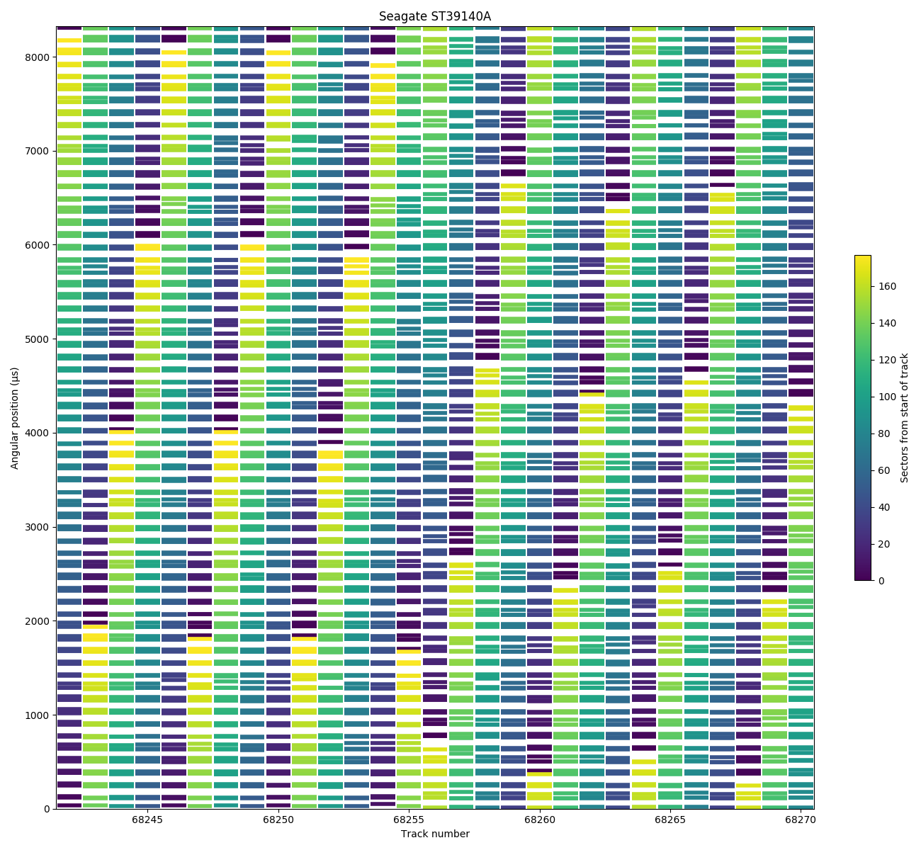
Angular position near a zone change: Zone change (track 68256) has unusual skew. All sectors appear aligned to 1/64 revolutions, causing groups of sectors to appear to be at the same angular position.
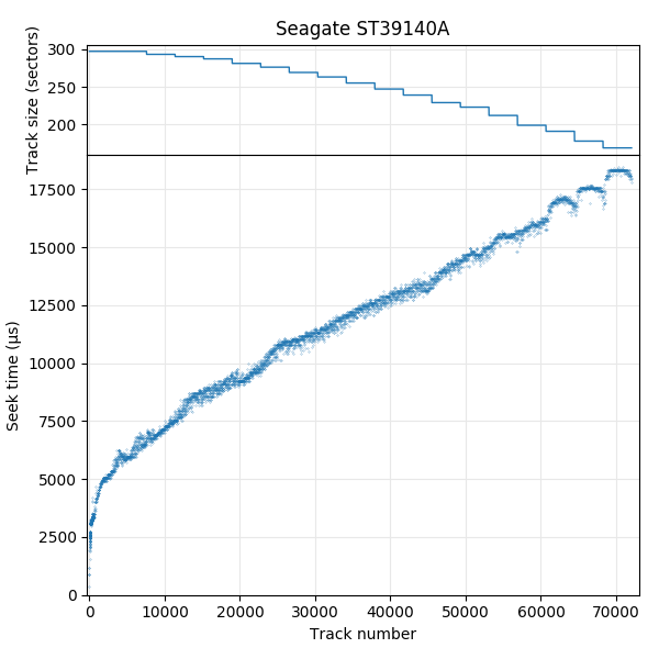
Seek profile
Looking at an angular-position plot reveals something suspicious about the previous track skew measurements. The drive seems to quantize (delay?) its response times for all sectors until an approximate multiple of 1/64 revolution (130 µs or 5.625°). This makes group of 3 to 5 sectors all appear to clump together in the same angular position. The track start positions being strictly aligned to multiples of 1/64 revolution may not actually be real, but I did verify that groups of 8 tracks do have a total skew within 0.1° of 127/64 revolutions.
The seek profile looks fairly typical.
The Product Manual (page 3) for this drive has some details about the internal characteristics of the drive. The table below shows a comparison between my measurements and the specifications in the manual.
| Microbenchmark | Specification | |
|---|---|---|
| Cylinders | 72048/8 = 9006 | 9006 |
| Read/Write heads | 8 | 8 |
| Data zones | 18 | 19 |
| Spindle speed (rpm) | 7209 | 7200 ± 0.5% |
| Linear density (kbpi) | 100 | 179.2 |
| Track density (tpi) | 8200 | 9570 |
| Track-to-track seek | 1.7 | 2.0 |
| Average read seek | 9.5 | 9.5 |
| Full stroke seek | 18.3 | 21 |
Some metrics match the manual, while some differ significantly. The fact that a precise number of cylinders is specified and that my measurements exactly match the specification suggests that sector slipping (which changes the size of a track, and thus the number of tracks) is simply not done on this drive.
The number of zones differs by one: I measure 18 regions of distinct track sizes, but the manual specifies 19 zones. Because the zone sizes are regular, I speculate that the first two zones (on my drive or this model) actually have the same density. Looking at the track size plot, the first “zone” is 7584 tracks (or 948 cylinders) in size, which is exactly double the other 17 zones (474 cylinders each).
The average density numbers I measure are much lower than specified in manuals (not just this drive). I can’t explain the gap, but the section on estimating track and bit density offered some possible explanations.
My measurement of the track-to-track and full-stroke seek times are both better than the specification, although the measured average seek time is the same as the specification.
Samsung SV0432D, 4.3 GB
| Samsung SV0432D | |
|---|---|
| Capacity | 4.3 GB |
| RPM | 5399 |
| Sectors (512B) | 8421840 |
| Sectors per track | 403 – 231 |
| Tracks | 24460 |
| Surfaces | 2 |
| Skew (°, rev) | 60° (7/42 rev) |
| Max. seek (ms) | 19.4 |
| Random access (ms) | 14.8 |
| Random seek (ms) | 9.2 |
| Avg. track pitch (TPI) | 11k |
| Avg. OD linear density (kbpi) | 150 |
| Track layout | |

Track size: 16 zones. Often one very small track immediately before a zone change

Track skew: 7/42 and 10/42 revolution skew.
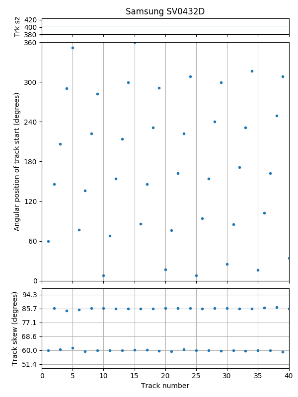
Track skew: 7/42 and 10/42 revolution skew alternates. There are two surfaces using a traditional head-first layout.
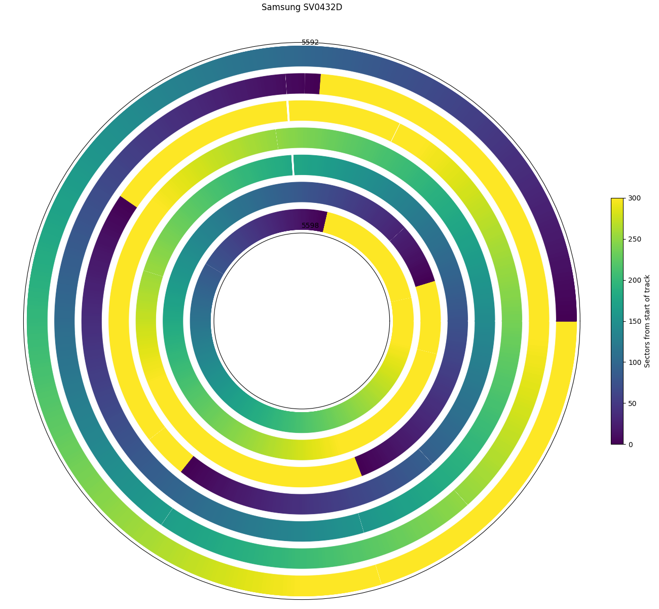
Hole in tracks 5594 and 5596. This suggests these two tracks are physically adjacent, which suggests a traditional type F layout instead of cylinder serpentine type A.
The Samsung SV0432D is a 4.3 GB hard drive. My particular drive has TriGem branding on the label, and I didn’t realize it was Samsung until fairly recently.
The track size plot shows 16 zones, sometimes with a partial (very small) track at the end of each zone. There are also some tracks that seem to be missing a few sectors (defects, sector slipping).
The track skew plot shows that all tracks are aligned to some multiple of 1/42 revolutions. Two skews are common: 7/42 (60°) and 10/42 (85.7°). Zooming in to the first 40 tracks shows that these two skews alterate. Combined with the seek profile, which does not show any seek-first layout features, this skew pattern suggests that the drive has two recording surfaces, and uses a head-first track layout, with one skew for a head switch, and a different skew for a next-track seek.
Two small (one-sector) defects on tracks 5594 and 5596 at the same angular position suggests that these two tracks are physically adjacent, which would lead to a traditional type F layout instead of cylinder serpentine type A. But since there are very few defects, this example only occurs once so this alone is not conclusive evidence. The seek time plot below provides additional evidence for a traditional type F layout.
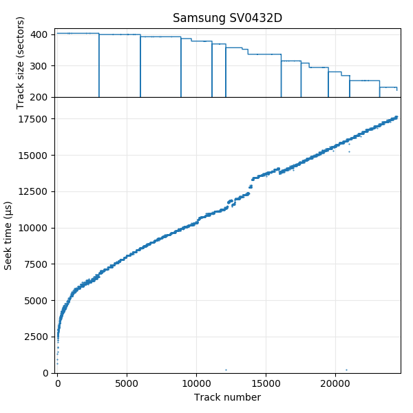
Seek profile

Seek profile, first 100 tracks. Lines join tracks on the same surface. There is around 250 µs head switch overhead.
The full-disk seek profile looks unremarkable. Zooming in to the first 100 tracks shows that the seek time to even-numbered tracks is noticeably lower than to odd-numbered tracks. In this plot, I drew two lines, connecting the odd points and even points. This shows that this drive has a rather high penalty for a head switch, not due to a large misalignment of tracks between surfaces (the graph is shifted up, not to the left or right). This alternating pattern, assuming the alternating pattern represents a head switch overhead, is additional evidence for a traditional (head-first type F) layout, which switches heads for every logical track change (type A would switch heads once every two tracks).
Seagate ST1, 5 GB
| Seagate ST1 ST650211CF | |
|---|---|
| Capacity | 5 GB |
| RPM | 3607 |
| Sectors (512B) | 9767520 |
| Sectors per track | 335 – 183 |
| Tracks | 37782 |
| Surfaces | 2 |
| Skew (°, rev) | Side 0: 109.3° (17/56 rev) Side 1: 116.7° (18/56 rev) |
| Max. seek (ms) | 26.3 |
| Random access (ms) | – |
| Random seek (ms) | – |
| Avg. track pitch (TPI) | 91k |
| Avg. OD linear density (kbpi) | 480 |
| Track layout | |
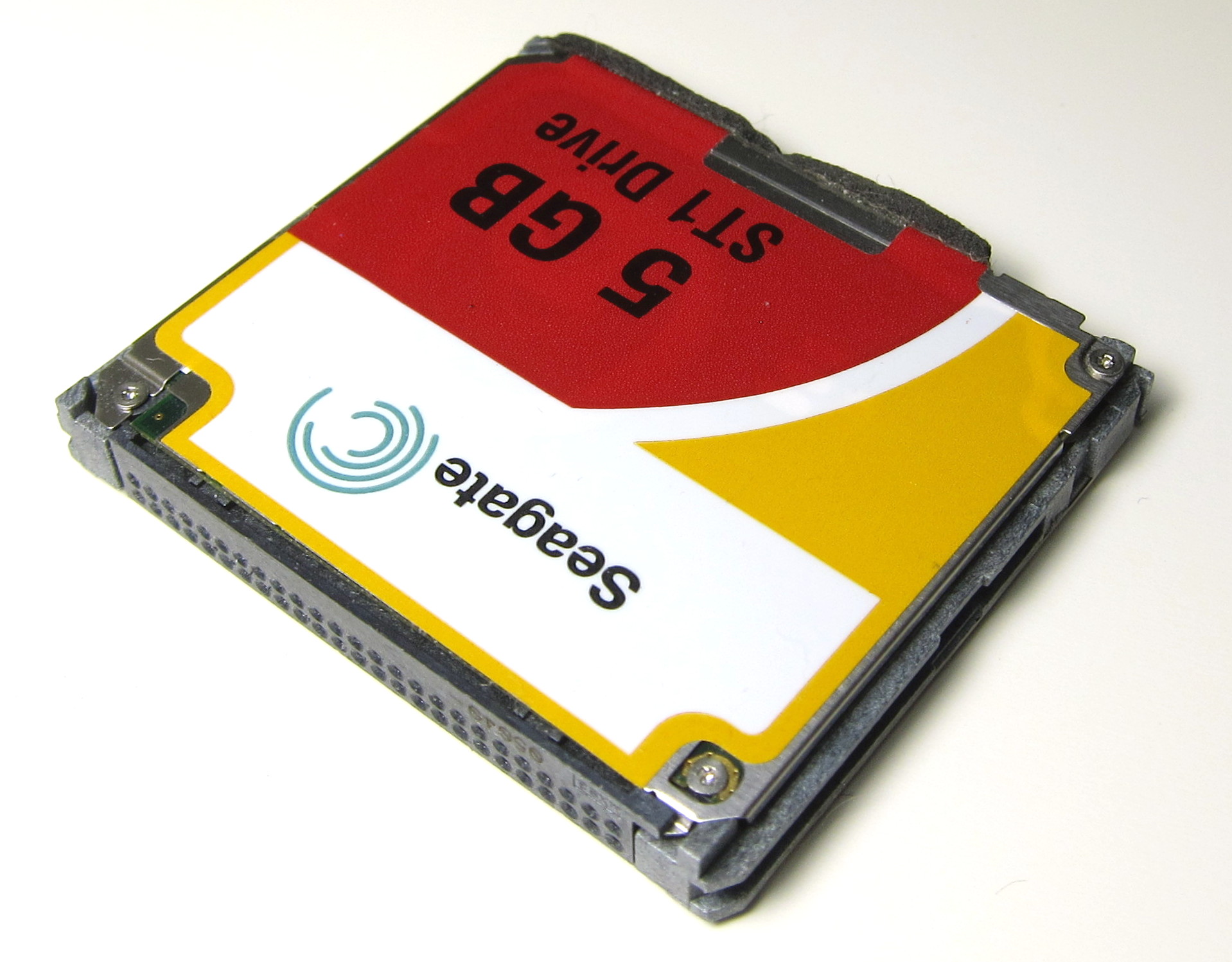
Seagate ST1: 1″ hard drive in CompactFlash Type II form factor.
The Seagate ST1 is a 5 GB (one platter) 1″ micro-drive. There are two models, one with a flex cable interface, and one with CompactFlash. My drive uses a CompactFlash interface, which is electrically compatible with a parallel ATA interface, which allows using a passive adapter to use it as a parallel ATA hard drive.

Track size: This drive switches heads/surfaces infrequently.
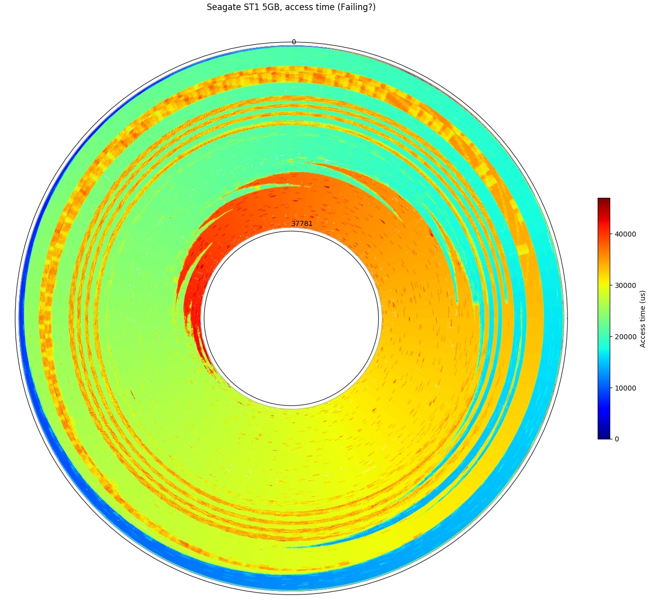
Access time, full disk: The drive seems to have trouble with seek accuracy. Many regions take one more revolution than expected. The drive is possibly failing: SMART reports a failure for Seek Error Rate.
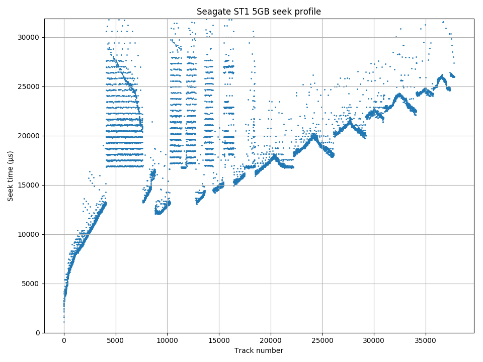
Seek profile: The frequent seek errors prevent a reliable seek profile measurement, although it is still good enough to see the important patterns.
The track size plot looks different from the plots seen so far. It does not monotonically decrease with logical track number. This drive has different density on the two surfaces, and switches surfaces fairly infrequently.
The Seagate ST1 full-disk access time plot has many regions and patterns where the access time is one or two revolutions longer than expected. My Seagate ST1 is likely defective, as its SMART attributes are reporting a failure for the “seek error rate” attribute. These seek errors also affect the accuracy of the seek time profile.
The seek time profile clearly shows some regions where the seek time is unexpectely slow. Some regions randomly take an unexpected extra revolution to read a sector, particularly when there is a head switch involved. This plot again illustrates the difficulty of designing microbenchmarking algoritms that are robust enough to work on imperfect test subjects. Fortunately, the plot still looks good enough to extract track layout information. It uses a surface serpentine (type AF) layout with very big serpentines (thousands of tracks).

Track skew: The two sides of the platter use different skew: 17/56 rev (109.3°) and 18/56 rev (116.7°).
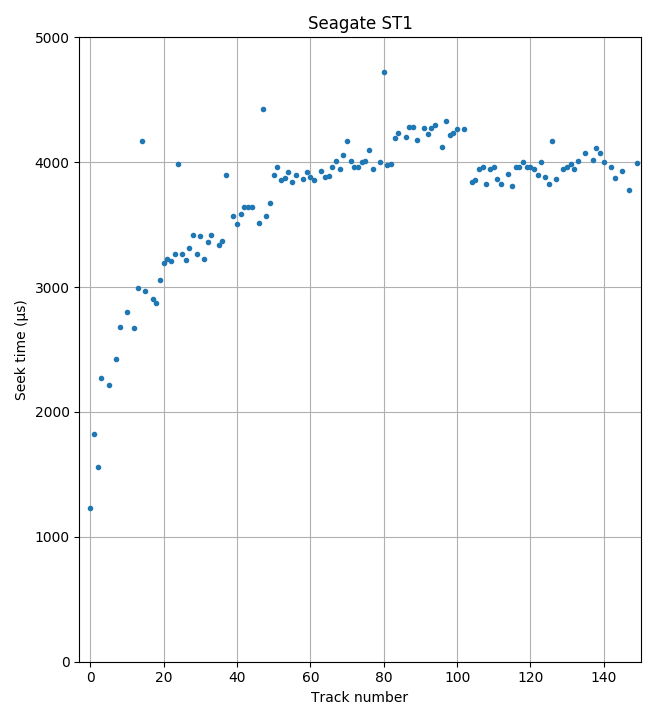
Seek profile, first 150 tracks. Adjacent track can be reached in about 1.8ms, including controller overhead (of >1 ms)
The track skew is unusual. This drive uses different skew for the two surfaces! It uses 17/56 revolutions for one side, and 18/56 revolutions for the other. The skew seems unnecessarily big (at least for reads). 17/56 revolutions is more than 5ms of skew at 3607 RPM, but the seek profile plot (zoomed in) clearly shows that a next-track seek is much faster than that (about 1.8 ms including controller overhead). 5 ms is enough for a seek distance of about 300 tracks.
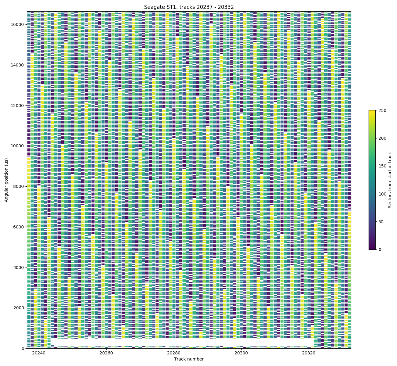
Angular position, tracks 20237 – 20332: There is a gap of approximately one sector at the end of each track, but it does not appear to be used for spare sectors. The gap exists even for the region with a block of defective sectors near angular position 300 µs.
An angular-position plot (plotted with track number on the horizontal axis and angular position on the vertical axis) shows that there is a gap of about one sector in size at the end of each track. I don’t know what that space is used for, but it appears to not be spare sectors. There is a fairly big defect visible near the bottom of the plot (big white rectangle spanning 6 sectors of tracks 20244 to 20321), but the gap at the end of each track remains and was not used to substitute for the defective sectors.
This drive is now completely dead. Its final contribution to science will not be forgotten. Its memory lives on in the plots above, to be appreciated by people all around the world.
Toshiba MK8034GSX, 80 GB
| Toshiba MK8034GSX | |
|---|---|
| Capacity | 80 GB |
| RPM | 5400 |
| Sectors (512B) | 156301488 |
| Sectors per track | 891 – 429 |
| Tracks | 219635 |
| Surfaces | 3 |
| Skew (°, rev) | 51.8° (19/132 rev) |
| Max. seek (ms) | 19.1 |
| Random access (ms) | 16.4 |
| Random seek (ms) | 10.8 |
| Avg. track pitch (TPI) | 109k |
| Avg. OD linear density (kbpi) | 480 |
| Track layout | |
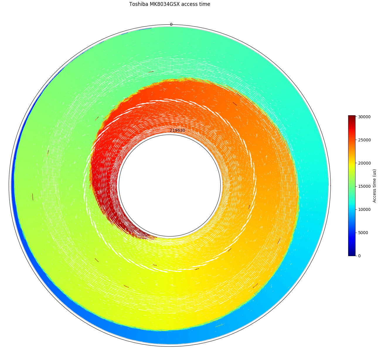
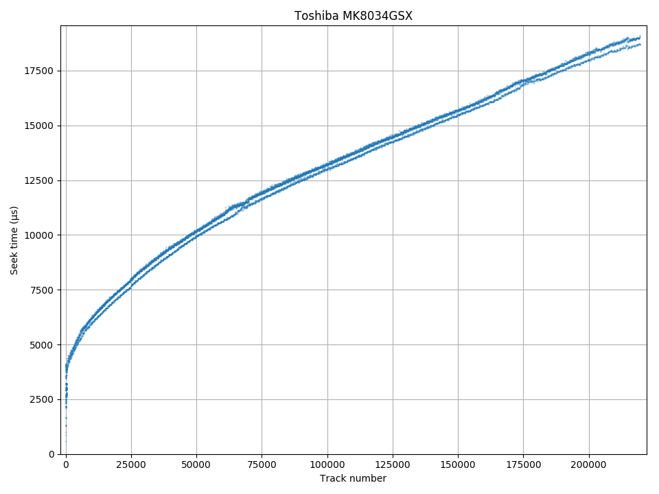
Access time, full disk

Track size: Every surface has the same track size.
The MK8034GSX is a 2.5″ laptop hard drive. The track size and seek profiles show no surprises. There are 20 zones of varying size, where all surfaces use the same track size, with no sign of reduced track size due to sector slipping for defects.
Seek profile
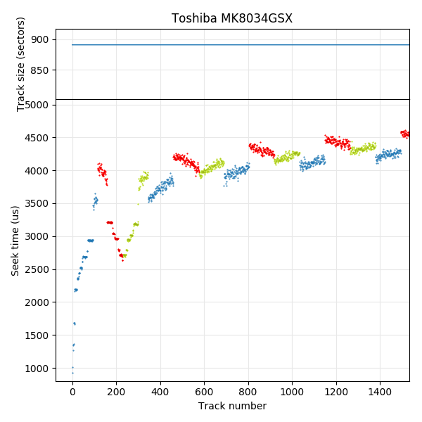
Seek profile, first 1500 tracks: 3 recording surfaces. Data points are coloured to highlight each of the three surfaces.
The seek profile appears to show two parallel lines. The lower line comes from seeks to sectors on the same surface as sector 0 (there is a head-switch penalty). Zooming in to the first 1500 tracks of the seek profile shows the track layout. This drive has three surfaces and uses a seek-first surface serpentine (type AF) layout. The data points corresponding to each surface are shown in a different colour. Track 0 is in the blue region, and all of the subsequent blue regions have lower seek time than for the other two regions. This pattern persists over the entire disk and is the reason for the two lines in the full-disk seek profile plot.
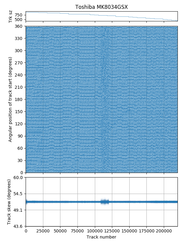
Track skew: 19/132 rev (51.8°)
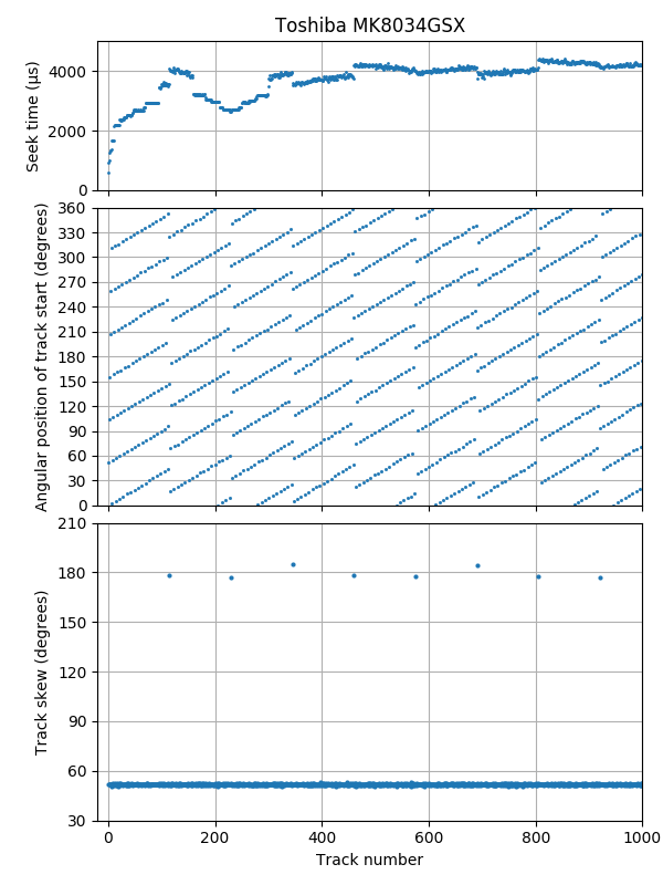
Track skew, first 1000 tracks: 180° skew at each serpentine boundary, 51.8° otherwise.
The track skew is 19/132 revolutions (51.8°), with a 180° skew at serpentine boundaries.
Hitachi Deskstar 7K80 HDS728080PLA380
| Hitachi 7K80 HDS728080PLA380 | |
|---|---|
| Capacity | 82 GB |
| RPM | 7201 |
| Sectors (512B) | 160836480 |
| Sectors per track | 1170 – 573 |
| Tracks | 176275 |
| Surfaces | 2 |
| Skew (°, rev) | 67.3° (3/16 -0.0004 rev) |
| Max. seek (ms) | 16.0 |
| Random access (ms) | 13.0 |
| Random seek (ms) | 8.7 |
| Avg. track pitch (TPI) | 81k |
| Avg. OD linear density (kbpi) | 430 |
| Track layout | |
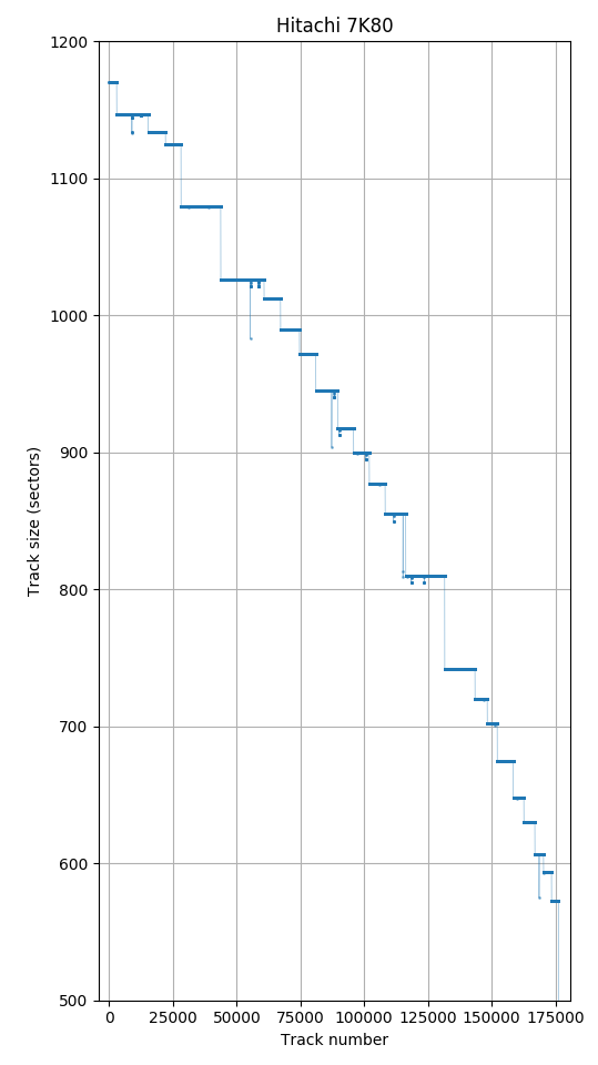
Track size
The 7K80 is a one-platter 80 GB drive released in 2005.
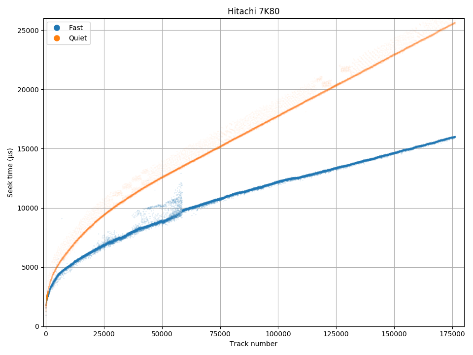
This drive has acoustic management (AAM). For unknown reasons, I found my drive in quiet mode and didn’t notice until measuring unexpectedly slow seek times.
The track size plot shows monotonically-decreasing track size with increasing track number (same track size on all surfaces), and signs of sector slipping for defects (a few tracks are a few sectors smaller than expected).
Seek profile
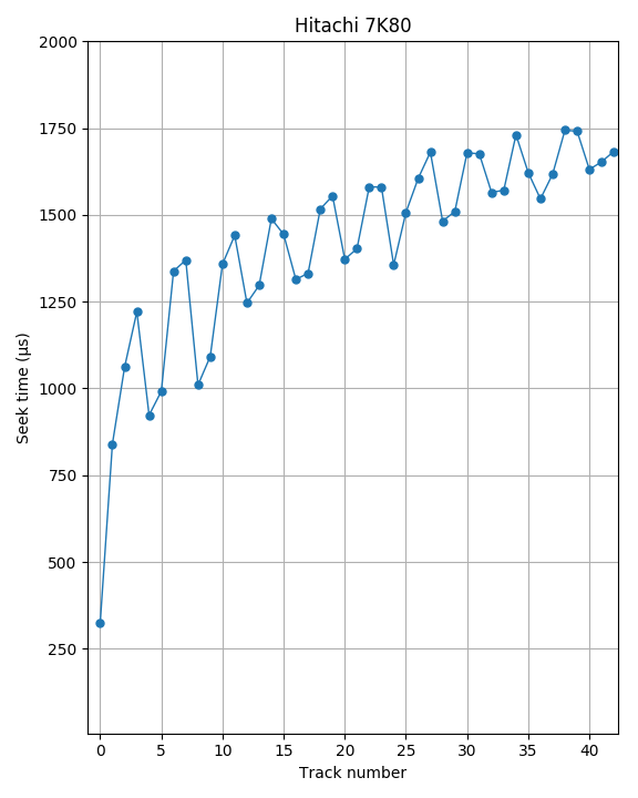
Seek profile, first 43 tracks. Groups of two suggest two-surface cylinder serpentine type A layout (alternating head switch and track switch)
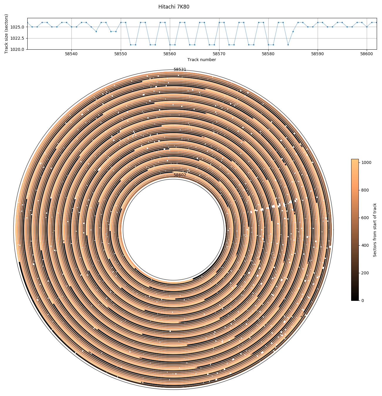
Defects near tracks 58552 to 58581 are in groups of two, suggesting pairs of tracks are placed on the same surface.
The seek profile shows no sign of serpentines, which suggests a head-first layout. The detailed seek profile shows higher and lower seek times in groups of two tracks. This suggests that there are two surfaces, that there is a head switch delay, and that tracks are organized so that it switches heads every two tracks. This is a cylinder serpentine (type A) layout rather than traditional (type F).
More evidence for a two-surface type A layout can be found by looking at patterns of defective sectors. A cluster of defects on tracks 58552 to 58581 show holes on pairs of tracks with two hole-free tracks in between (hole size is 5 sectors, which causes the track size to decrease from 1026 to 1021 sectors). Since the holes are all at the same angular position, it is likely this is a single defect spanning adjacent physical tracks on the same surface, while the hole-free tracks are on a diferent surface. If this were a type F layout, the holes would occur on every other track rather than one pair every four tracks.

Track skew: Every 4095 tracks, there is one track with doubled skew. But this doesn’t correspond to zone boundaries.
The track skew is approximately 67.3° (slightly less than 3/16 revolution). There is one 135° skew that occurs every 4095 tracks. Usually this kind of pattern marks some kind of cylinder, serpentine, or zone boundaries, but this doesn’t appear to be the case here. The zone boundaries are not related to multiples of 4095 tracks.
There is a specification book!
This hard drive model has a specifications book that has a surprising amount of detail about this drive. The following two tables compares some of the microbenchmark measurements with the specifications.
| Microbenchmark | Specifications | |
|---|---|---|
| Sectors per track | 1170 – 573 | 1170 – 567 |
| Linear density (kbpi) | 430 (outer track) | 689 max |
| Track density (tpi) | 81k avg | 90k |
| Average read seek, fast (ms) | 8.7 | 8.5 (9.5 max) |
| Average read seek, quiet (ms) | 12.7 | 19.5 (20.5 max) |
| Full stroke read seek, fast (ms) | 16.0 | 15.1 (18.1 max) |
| Full stroke read seek, quiet (ms) | 25.7 | 32.5 (35.5 max) |
| Head switch (skew) (ms) | 1.50 – 1.61 (65.0°-69.7°) | 1.4 (60.5°) |
| Cylinder swich (skew) (ms) | 1.7 (73.4°) |
As usual, my estimates of average density (linear and track density) are quite a bit lower than the (max) numbers quoted in the specifications, and I cannot explain much of the difference.
The measured seek times in fast mode are slightly worse than the claimed “Typical” seek times, but well within the “Maximum” seek time specifications. One caveat is that the manual’s definition of seek time differs slightly from mine.
My computation for average seek time is to measure the average access time, then subtract average latency (half rotation period) and command overhead, but command overhead cannot be directly measured. The specifications book defines command overhead to be the cache-miss delay without any seek or settling time. There are two related actions that I can measure. I can measure the minimum time to read a sector (~0.36 ms), but this may include some settling time on top of the command overhead. I can also measure the cache hit access time (0.09 ms), but according to the manual, the command overhead for a cache hit is lower than for a cache miss (specification: 0.3 ms vs. 0.1 ms). I chose to use the cache-hit time as my approximation of command overhead, as some drives have such a big difference between cache hit and miss that I find it hard to believe the minimum cache miss response time is a reasonable approximation of command overhead (e.g., the WD S25 has a response time of 0.08 ms for a cache hit, but minimum 1.2 ms for a cache miss).
The measured quiet mode seek times (full stroke and random) are much faster than specified.
The specification book specifies two different values for head and cylinder skew (1.4 ms and 1.7 ms). I was not able to detect any difference between head and cylinder skew. The 5th and 95th percentile of the skews are 1.50 ms and 1.61 ms, whereas the specification would suggest the skews should alternate between 1.4 ms and 1.7 ms (there are two surfaces, so head switch and cylinder switch alternates). However, the average skew (50% track skew, 50% cylinder skew) is a near perfect match (1.56 ms vs. 1.55 ms).
The following table compares zone sizes (in cylinders) and the number of sectors per track in each zone. My microbenchmark measurements mostly match the list in the specification book.
| Microbenchmark | Specifications | ||
|---|---|---|---|
| Cylinders (Tracks/2) |
Sectors/Track | Cylinders | Sectors/Track |
| 1443.5 | 1170 | 1444 | 1170 |
| 6188.5 | 1147 | 3095 | 1147 |
| 3095 | 1147 | ||
| 3388 | 1134 | 3389 | 1134 |
| 3042.5 | 1125 | 3043 | 1125 |
| 7789 | 1080 | 3845 | 1080 |
| 3946 | 1080 | ||
| 8500 | 1026 | 4501 | 1026 |
| 4001 | 1026 | ||
| 3231 | 1012 | 3232 | 1012 |
| 3725 | 990 | 3726 | 990 |
| 3192.5 | 972 | 3193 | 972 |
| 4285 | 945 | 4286 | 945 |
| 3119 | 918 | 3120 | 918 |
| 3092.5 | 900 | 3093 | 900 |
| 3105 | 877 | 3106 | 877 |
| 4036 | 855 | 4037 | 855 |
| 7644 | 810 | 4073 | 810 |
| 3573 | 810 | ||
| 5949.5 | 742 | 3276 | 742 |
| 2675 | 742 | ||
| 4367 | 720 | 2408 | 720 |
| 1960 | 702 | ||
| 3135.5 | 675 | 1568 | 675 |
| 1568 | 675 | ||
| 2081.5 | 648 | 2082 | 630 |
| 2156.5 | 630 | 2157 | 630 |
| 1699.5 | 607 | 1700 | 607 |
| 1569.5 | 594 | 1570 | 594 |
| 1396.5 | 573 | 1521 | 567 |
When there are two consecutive zones with the same size, I have no way to measure the boundary between them, so I just report it as one big zone.
The measured size of each zone is always around one cylinder less than specified. I don’t have an explanation for this. There does not appear to be any hidden/spare tracks in between zones (which would likely show up as an unually big skew). Some of the zones have an odd number of tracks (thus, not a multiple of a cylinder), but even zones with an even number of tracks are usually one cylinder smaller than specified.
There are three zones where the specified sectors per track differ from the measurement (720, 648, and 573, bolded). The final zone is only partially used because the disk ends at the specified number of total sectors before filling the final zone.
Western Digital Caviar SE16, 250 GB
| Western Digital Caviar SE16 WD2500KS | |
|---|---|
| Capacity | 250 GB |
| RPM | 7204 |
| Sectors (512B) | 488397168 |
| Sectors per track | 1116 – 630 |
| Tracks | 520449 |
| Surfaces | 6 |
| Skew (°, rev) | 40° (2/18 rev) |
| Max. seek (ms) | 17.4 |
| Random access (ms) | 13.5 |
| Random seek (ms) | 9.2 |
| Avg. track pitch (TPI) | 79k |
| Avg. OD linear density (kbpi) | 410 |
| Track layout | |
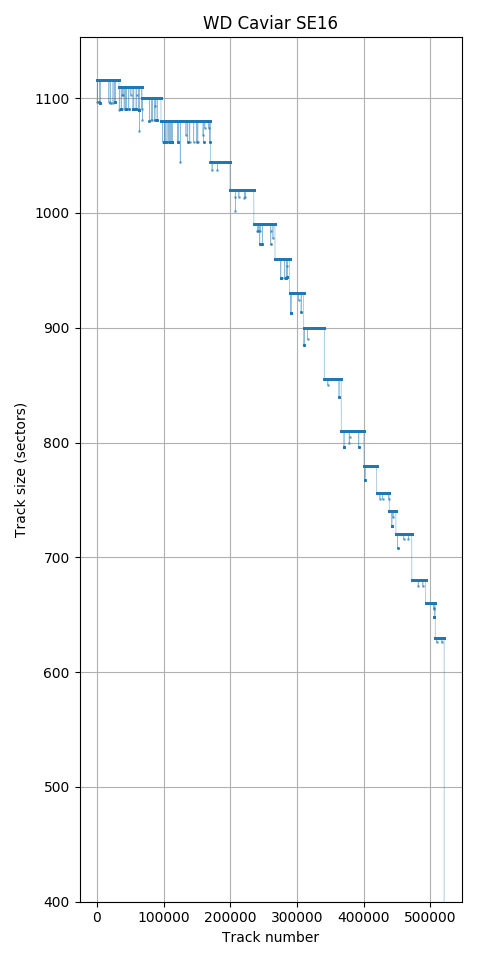
Track size
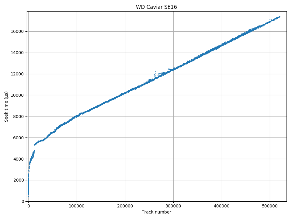
Seek profile
The Western Digital SE16 is a 3.5″ hard drive from 2005.
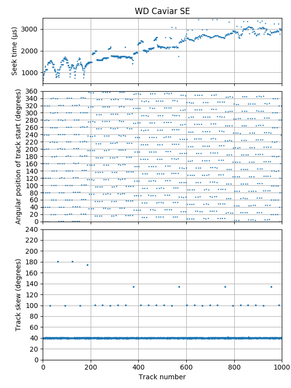
The track size plot shows monotonically-decreasing track size with increasing track number (same track size on all surfaces), and a random scattering of smaller tracks from sector slipping defects.
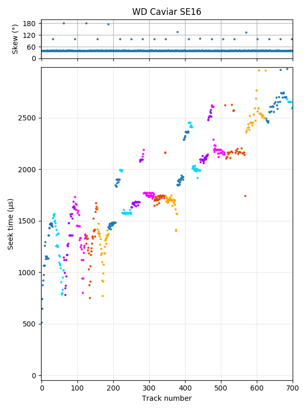
Seek profile, first 700 tracks. There are 6 surfaces, using surface serpentine layout.
Big defect presumed to span adjacent physical tracks on the same surface. It appears to occur every 6 logical serpentines, indicating that surfaces are cycled in the same order. The tracks with large skew delimit serpentine boundaries.
The beginning of the seek profile shows 6 recording surfaces using a surface serpentine (type AF) layout. The track layout can be distinguished from type AA by looking at the seek profile (the 12th serpentine matches better with the 6th serpentine than the first), or by looking for a big defect that spans multiple serpentines (e.g., tracks 62536 – 63143 where the hole repeats every 6 serpentines showing that the six surfaces are cycled through in the same order).
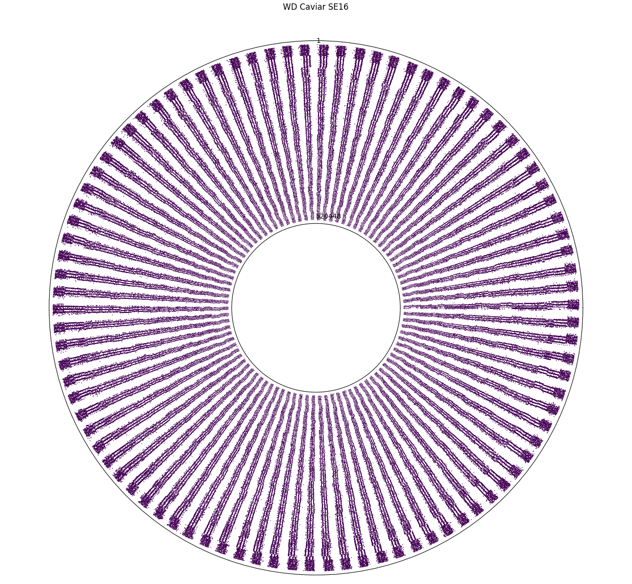
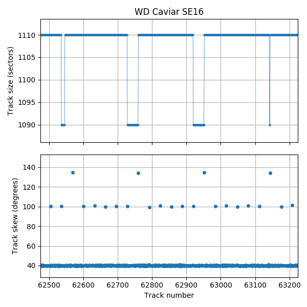
Track skew, polar plot.
Track skew, first 1000 tracks. There is a bigger skew every serpentine switch.
A track skew polar plot shows the angular position of the first sector of every track on the disk. It is the same data as the middle subplot in the normal (cartesian) track skew plot. The track starts tend to fall near multiples of 1/90 revolutions (4°).
Serpentine boundaries seem to be delimited by a bigger track skew. Except for the first 6 serpentines of the disk, the track skew appears to be 2/18 revolutions (40°), with slightly over 5/18 revolution (100.3°) skew for a serpentine change, and about 134.5° every 6 serpentines.
Acoustic Management
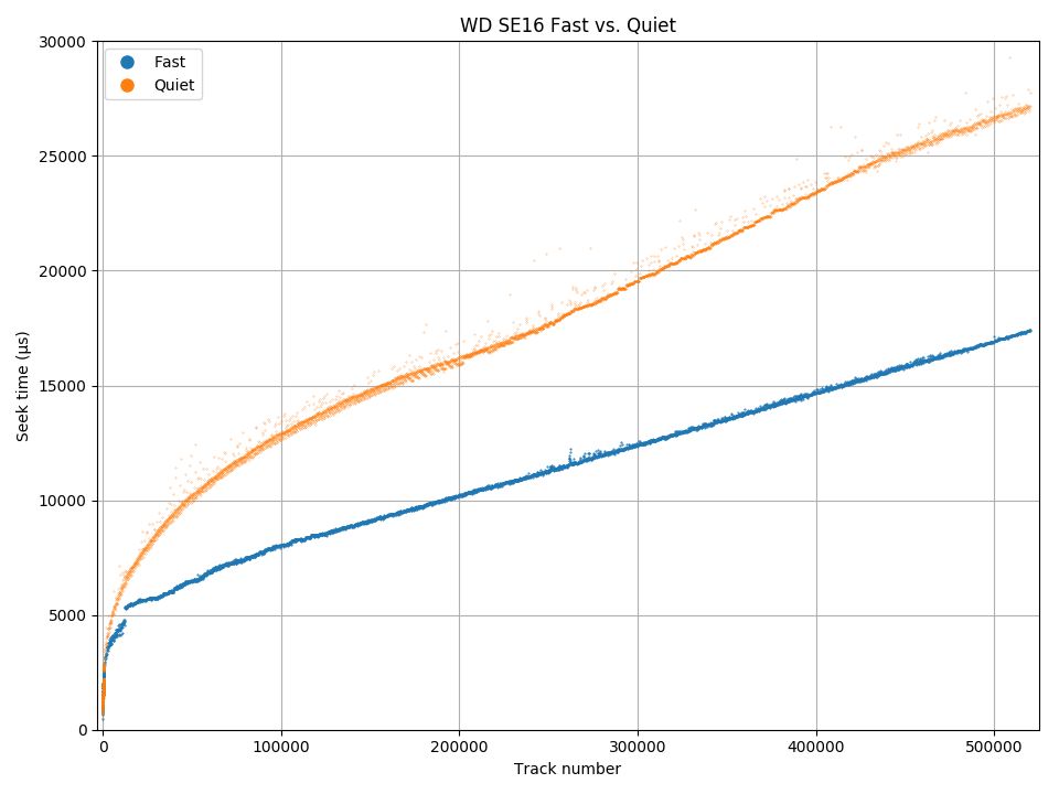
Acoustic management makes seeks slower.

Acoustic management does not affect the seek time for short-distance seeks.
This disk has acoustic management, with two levels of seek speed. The full-stroke seek time is 17.4 ms in fast mode and 27.1 ms in quiet mode. The zoomed-in seek profile shows that the acoustic management setting does not affect short seeks (below 2.25 ms).
Seagate Barracuda 7200.9, 160 GB
| Seagate Barracuda 7200.9 ST3160811AS | |
|---|---|
| Capacity | 160 GB |
| RPM | 7203 |
| Sectors (512B) | 312579695 |
| Sectors per track | 1452 – 638 |
| Tracks | 281786 |
| Surfaces | 2 |
| Skew (°, rev) | 55.7° |
| Max. seek (ms) | 24.1 |
| Random access (ms) | 17.5 |
| Random seek (ms) | 13.3 |
| Avg. track pitch (TPI) | 128k |
| Avg. OD linear density (kbpi) | 530 |
| Track layout |  |
Track size
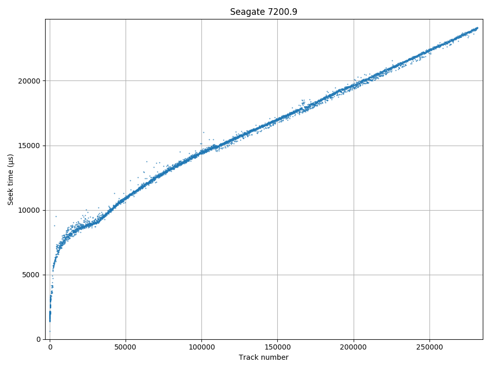
Seek profile
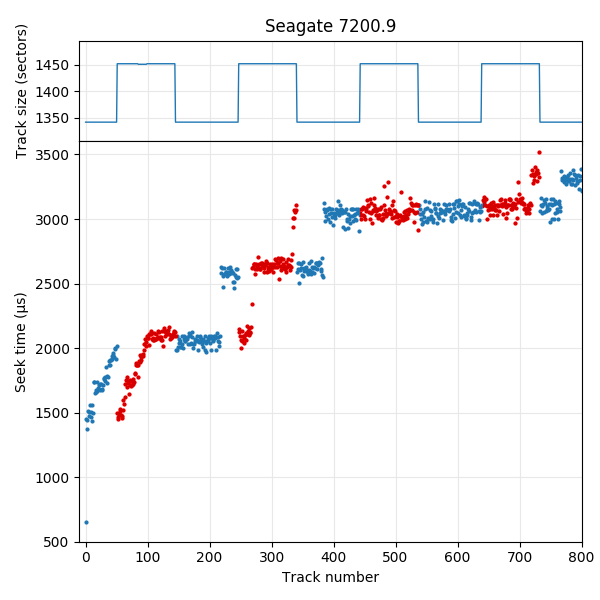
Seek profile, first 800 tracks. There are two surfaces, plotted in red and blue.
The track size plot shows that different surfaces have different track sizes. For example, the two surfaces in the first (outer-most) zone uses 1452 and 1342 sectors per track, respectively. Plotting the seek profile and track size plots on the same axis shows the track layout. The disk has two surfaces. In this plot, the seek profile points for each surface are coloured red and blue. All serpentines are laid out from outside to inside, and the surface ordering reverses after every group of two surfaces (0, 1, 1, 0, 0, 1, …). The track layout is seek first, type FA.
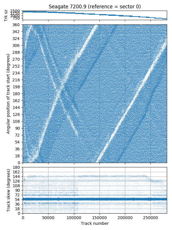
Track skew. What’s this weird pattern?
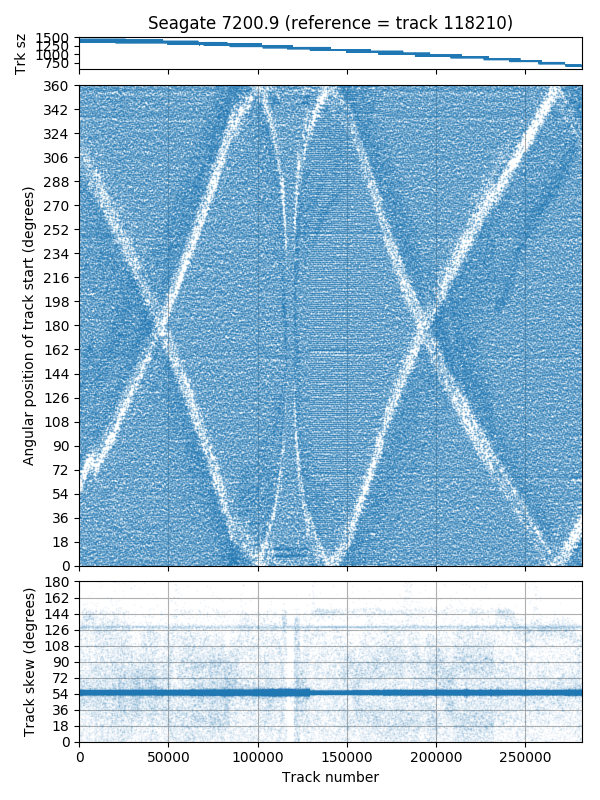
Track skew, reference = track 118210. The pattern is different…
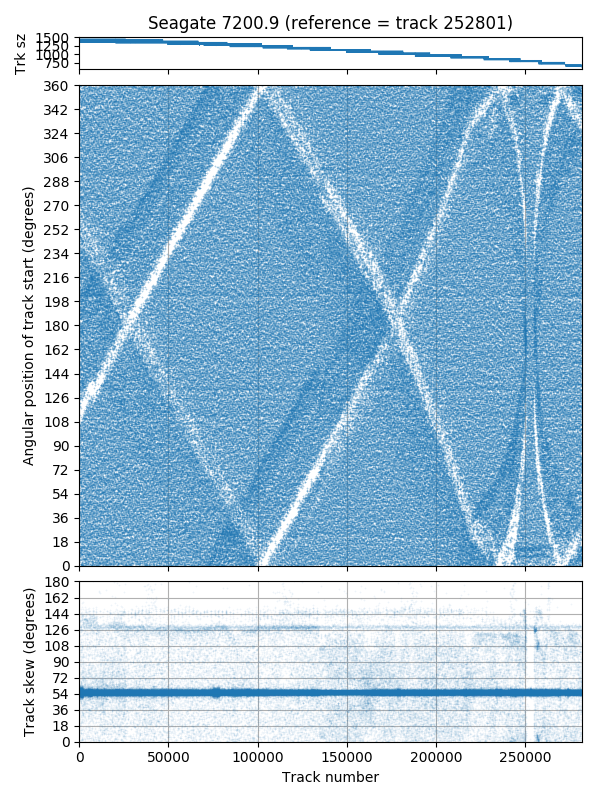
Track skew, reference = start of track 252801. The pattern is different…
The track skew plots (middle subplot) looks unusual, with big white lines through what would usally be a fairly uniform pattern. The white region might inidcate that those regions don’t contain the beginning of any track (Defective? Strange track skew?). It turns out that these patterns actually do not represent the location of sectors on the disk, but are actually measurement errors. In the first track skew plot, the start sector of each track is measured relative to sector 0 on the disk (The access time between sector 0 and the start sector of each track is measured). The second and third plots change this reference sector to a sector near the middle and end of the disk. The track skew measurements should be the same regardless of the reference sector used. If the white patterns truly represented the locations of sectors on the disk, the patterns should also be the same. Instead, the pattern changes.
The shape of the white band of sectors seems to resemble the seek profile, wrapped around vertically at the revolution period (8330 µs). It appears that for sectors that pass under the head near when the head arrives, there is an extra delay. However, this delay is variable and mostly around 285°, not exactly one (or more) revolution(s). I cannot explain why the delay is not a multiple of a revolution. A sector passes under the disk head at predictable intervals (exactly the revolution period). If a sector read is delayed by a different amount, it implies that the sector was actually read from the disk at the expected time, but the response to the read command is delayed for other reasons.
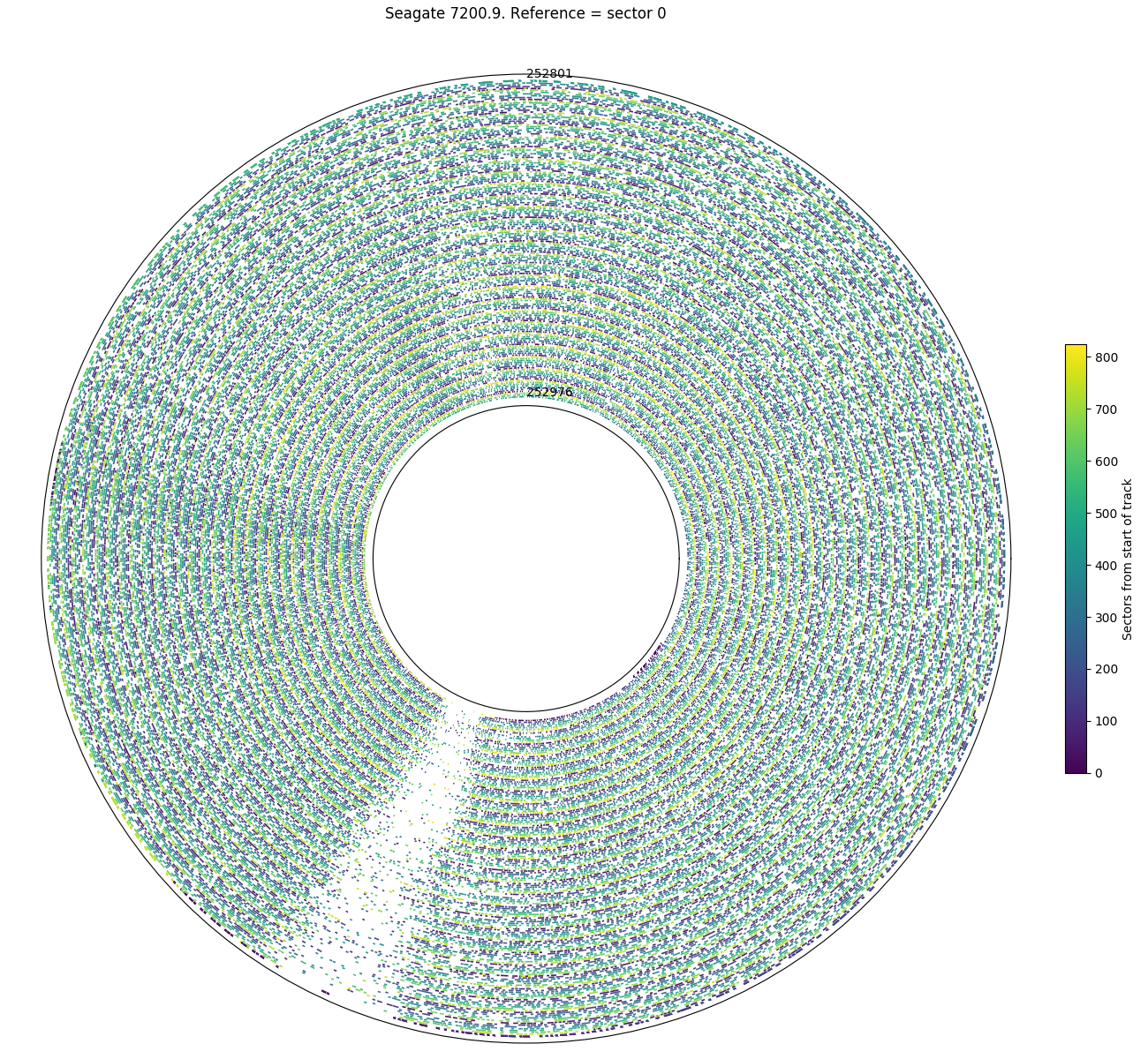
Angular position, as measured from reference sector = 0. Many sectors from angles near 245° are “missing”
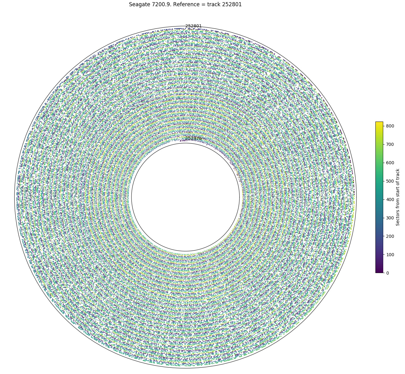
Angular position, as measured from the start of track 252801. All the sectors are still in their expected positions…

Difference in angular position for each sector for the two different reference points. Most sectors have the same angular position (0° ± noise), but the “missing” sectors are actually delayed by around 283° – 370°.
The above three plots show the angular position of all sectors in one small region of the disk that is affected by the band of missing sectors (tracks 252801 – 282976). The first plot shows that all sectors in the white band region are affected, not just the first sector of each track. The second plot shows the same region of the disk, but the angular position is measured from a reference sector nearby (first sector of track 252801), which minimizes the head seek. All of the sectors are at their expected locations and the white band not longer exists. The third plot shows the difference in the angular position measurement for every sector. Ideally, all sectors should have the same angular position regardless of which sector is used as the reference (showing a difference of 0). Instead, we see that there are sectors that differ by around 280° to 365°, with a cluster near 285°.
Seagate Barracuda 7200.11, 320 GB
| Seagate Barracuda 7200.11 ST3320613AS | |
|---|---|
| Capacity | 320 GB |
| RPM | 7204 |
| Sectors (512B) | 625140335 |
| Sectors per track | 2464 – 1200 |
| Tracks | 329853 |
| Surfaces | 2 |
| Skew (°, rev) | 61.3° (1/6 +0.004 rev) |
| Max. seek (ms) | 19.9 |
| Random access (ms) | 19.4 |
| Random seek (ms) | 15.1 |
| Avg. track pitch (TPI) | 150k |
| Avg. OD linear density (kbpi) | 900 |
| Track layout | |
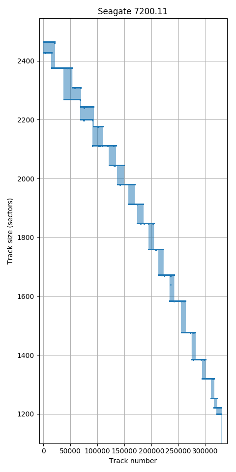
Track size
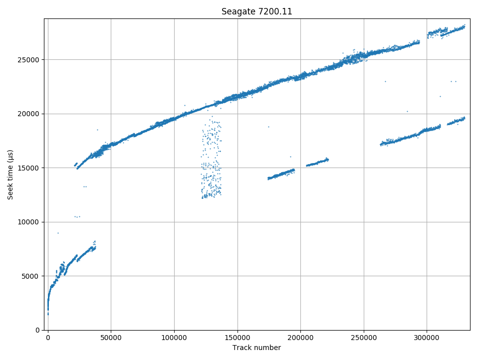
Seek time: Much of the disk takes an extra revolution to seek.
The track size plot has no surprises. The seek time plot shows something wrong. Much of the disk seems to take one extra revolution after a seek. This is not simply a seek that takes unusually long to settle, but a normal-speed seek and read of the target sector followed by around one-revolution of delay before the read command completes.
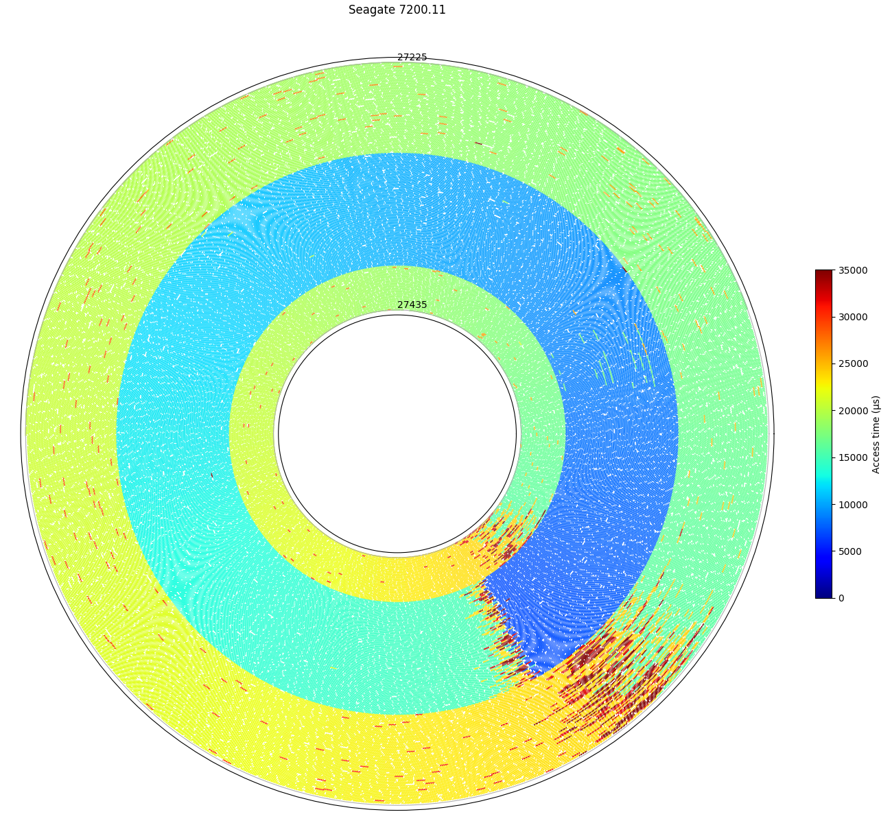
Access time from sector 1200 to tracks 27225-27435: This drive has regions where seeks take one or more revolutions longer than it should.
This plot shows the measured access time for every sector on tracks 27225 – 27435, which is one region that contains both “fast” and “slow” tracks. The middle region coloured green-blue (tracks 27304 – 27397) has the expected access time, while the other tracks take slightly over one revolution more to access. I don’t have an explanation for this behaviour. (I do have a second drive of the same model, but have not tested whether it behaves the same way.)
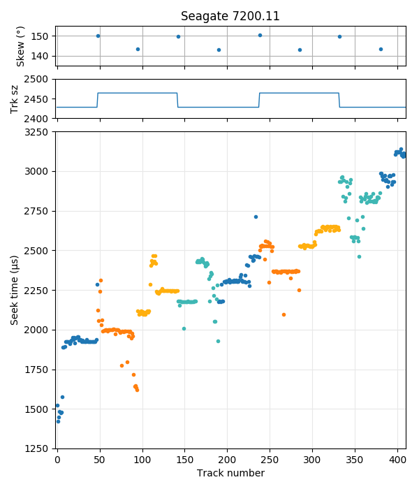
Seek profile, first 400 tracks. There are two surfaces (coloured blue and red/orange), and uses a seek-first (type AA) layout. A head switch has higher skew than jumping to the next serpentine on the same surface.
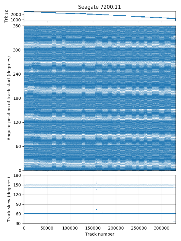
Track skew
The seek profile shows a two-surface seek-first track layout, with both out-to-in and in-to-out serpentines (types AF or AA). The track size plot shows that a head/surface change only occurs every two serpentines, so this drive uses a type AA layout. The serpentines coloured dark blue and orange are in the forward direction, while the red and teal coloured serpentines are in the reverse direction.
Track skew is slightly over 1/6 revolutions (61.3°), with a larger skew at serpentime boundaries (143.2° for same head, 150° for a head switch).
Western Digital S25, 300 GB
| Western Digital S25 WD3000BKHG | |
|---|---|
| Capacity | 300 GB |
| RPM | 10000 |
| Sectors (512B) | 585937500 |
| Sectors per track | 1926 – 1117 |
| Tracks | 384085 |
| Surfaces | 3 |
| Skew (°, rev) | 24.4° (1/15 +0.0009 rev) |
| Max. seek (ms) | 8.1 |
| Random access (ms) | 7.2 |
| Random seek (ms) | 4.2 |
| Avg. track pitch (TPI) | 250k |
| Avg. OD linear density (kbpi) | 1000 |
| Track layout |  |

Full-disk access time: Furthest sector is about 2.3 revolutions away. The irregular striped boundary indicates an unusual mapping from tracks to platters.
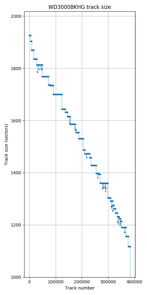
Track size monotonically decreases (except for defects).
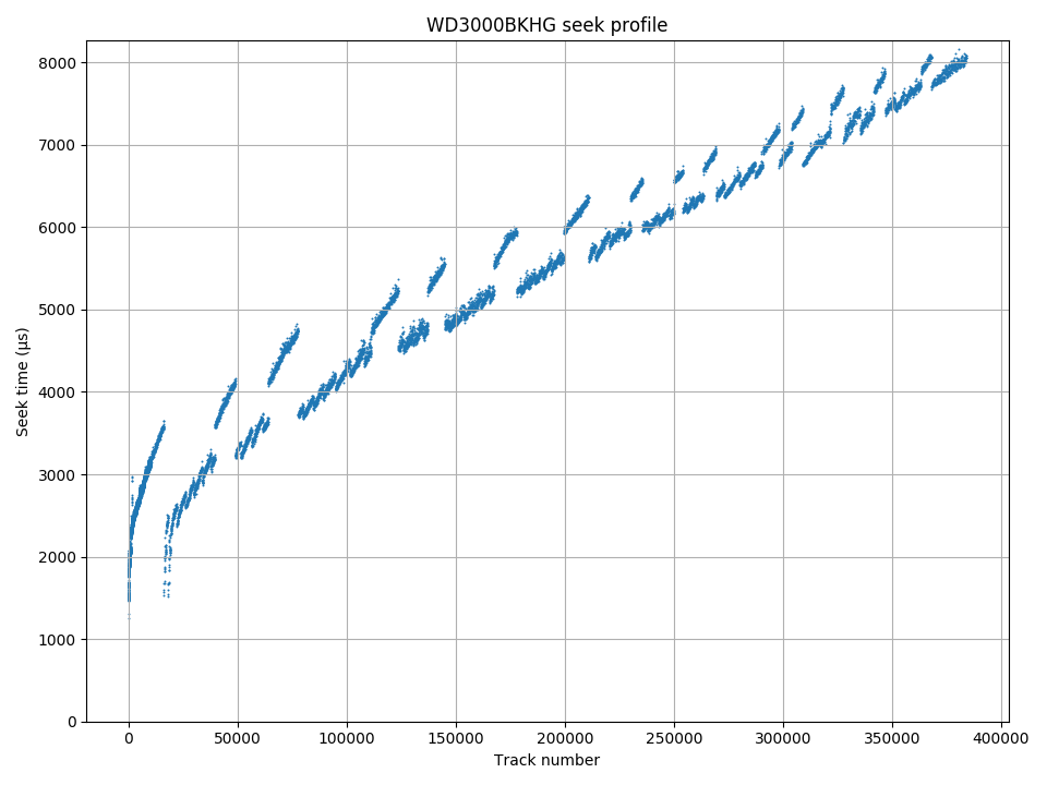
The seek profile is unusual, indicating an irregular mapping between track numbers and physical location.
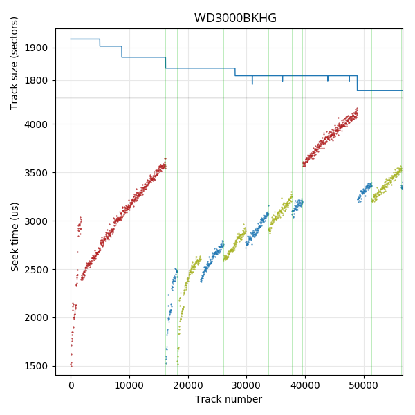
Seek profile, first 55,000 tracks. There are three recording surfaces. These are shown in different colours in the seek profile.
The track size plot shows that track size decreases monotonically. This looks unusual for a drive of this density, as other drives use surfaces that have different track sizes which causes the track size to vary whenever a head switch happens. It turns out that this drive does use different track sizes on each surface as expected, but orders the logical tracks so that track sizes decrease monotonically. This results in head switches at irregular intervals.
The seek time plot shows three recording surfaces. The zoomed-in plot shows a seek profile and track size plot on the same axis, coloured according to recording surface. The first recording surface is used for the first 16208 logical tracks, spanning 3 zones (1926, 1904, 1870 sectors/track). It then alternates between the two other surfaces (logical tracks 16208 to 39599, track sizes 1836 and 1813) before returning to the first surface (track size 1813). It appears that the first surface on this drive has higher density than the other two surfaces, which causes the first surface’s tracks to be placed earlier in logical track order.
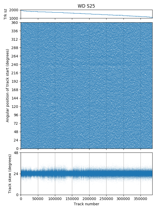
Track skew
The track skew is around 24.4°. There does not seem to be any systematic skew value when changing surfaces. There are randow skew values at random tracks scattered across the disk.
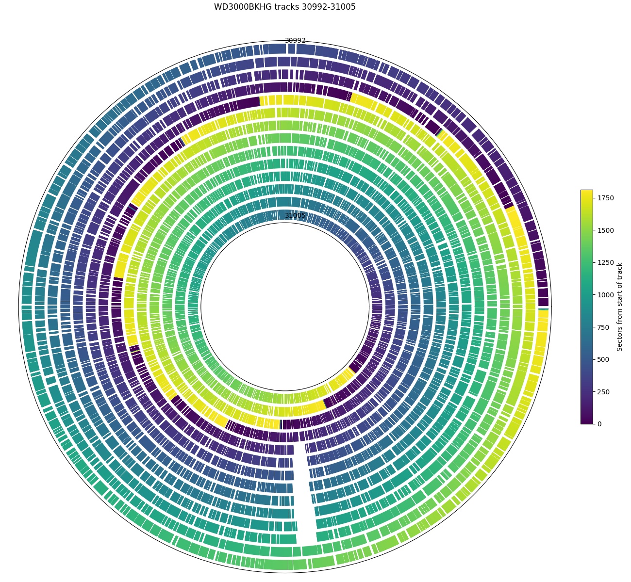
Angular position, tracks 39002 – 31005. There is a 27-sector hole spanning 8 tracks (1786 sectors per track vs. 1813) at roughly the same angular position.
This plot shows an example of a defect and sector slipping. The hole spans 27 sectors and 8 consecutive tracks.
Seagate Cheetah 15K.7, 450 GB
| Seagate Cheetah 15K.7 ST3450857SS | |
|---|---|
| Capacity | 450 GB |
| RPM | 15048 |
| Sectors (512B) | 879097968 |
| Sectors per track | 1800 – 1028 |
| Tracks | 595848 |
| Surfaces | 6 |
| Skew (°, rev) | 23.8° (1/15 -0.0006 rev) |
| Max. seek (ms) | 7.3 |
| Random access (ms) | 5.6 |
| Random seek (ms) | 3.5 |
| Avg. track pitch (TPI) | 174k |
| Avg. OD linear density (kbpi) | 900 |
| Track layout | |
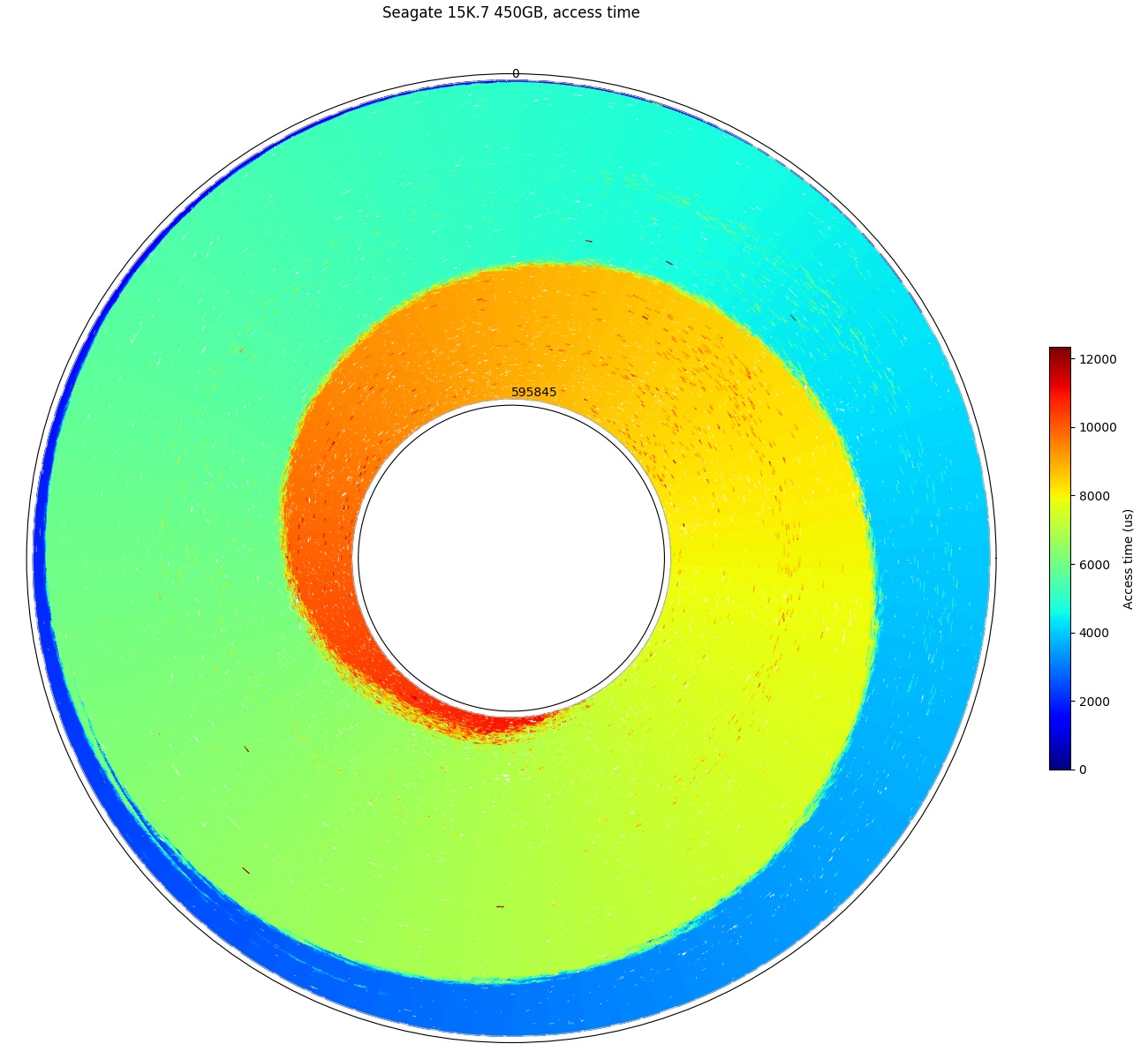
Full disk access time: The furthest sector is about 2.8 revolutions (at 15K RPM) away.
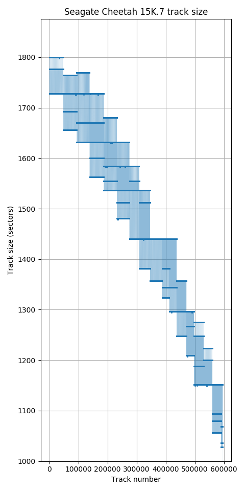
Track size
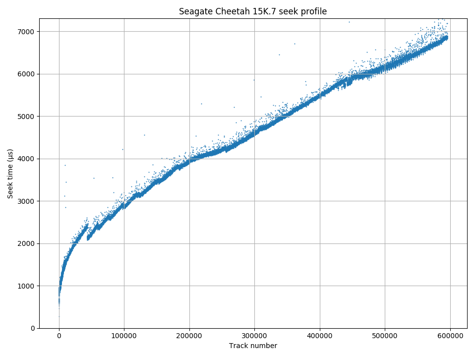
Seek profile. The small discontinuities appear to be related to the seek algorithm rather than track layout.
The track size is different on different platters. This makes it easy to identify the track layout.
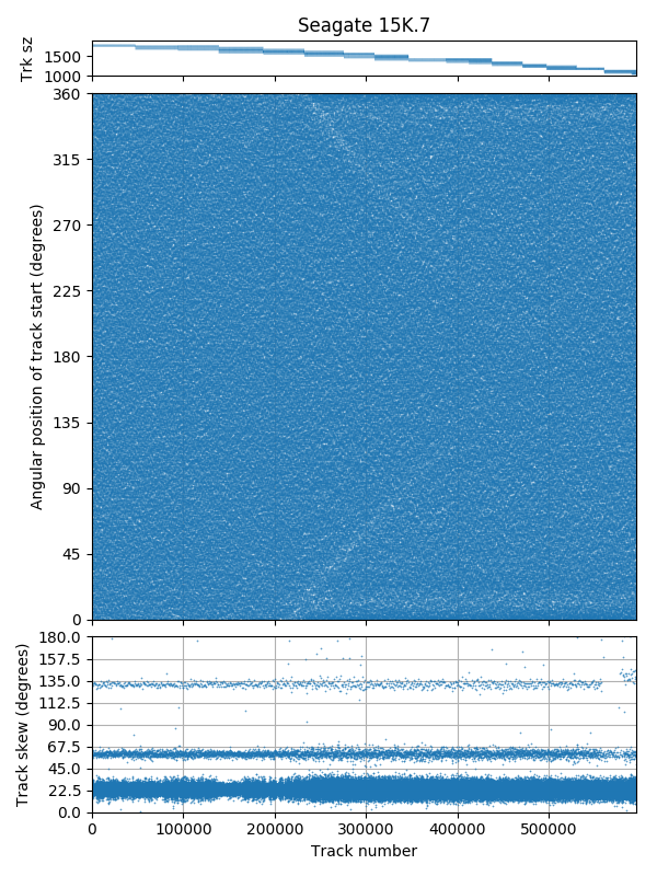
Track skew
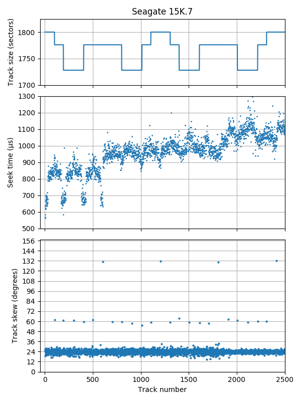
Track skew, first 2500 tracks: Tracks with bigger skew (60°, 132°) mark serpentine boundaries.
The track skew is around 23.8° (slightly less than 1/15 revolution), with a 60° skew at serpentine boundaries and 132° skew after each group of 6 serpentines. This disk has 6 recording surfaces. Because different surfaces have different track size, it is easy to see that the sequence of surfaces used reverses after every group of 6, which indicates a type AA layout, not type AF.
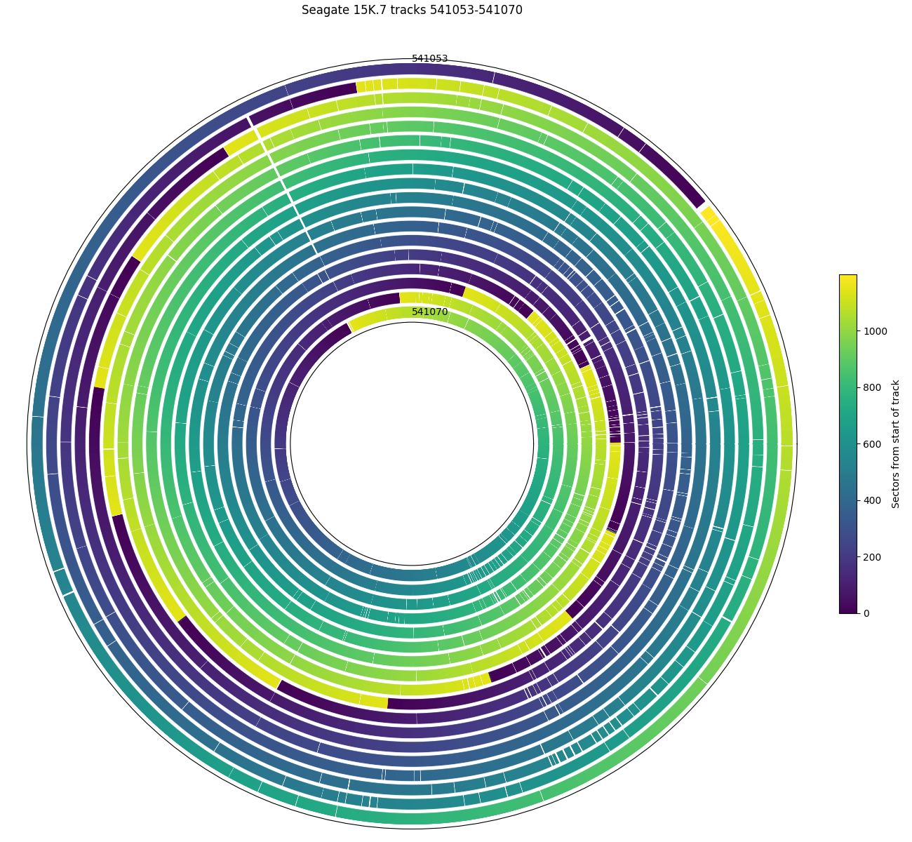
Angular position, tracks 541,053 – 541,070. There is a 2-sector hole spanning 11 tracks.
The plot above shows a 2-sector hole spanning 11 tracks. As can bee seen in the track size plot, this disk has very few tracks with defects, and there appears to be no tracks with more than two defective sectors. I speculate that if there are more than two defective sectors on a track, the entire track is skipped.
Samsung SpinPoint F3, 1 TB
| Samsung Spinpoint F3 HD103SJ | |
|---|---|
| Capacity | 1 TB |
| RPM | 7247 |
| Sectors (512B) | 1953525168 |
| Sectors per track | 2937 – 1546 |
| Tracks | 854135 |
| Surfaces | 4 |
| Skew (°, rev) | 72° (1/5 rev) |
| Max. seek (ms) | 17.3 |
| Random access (ms) | 13.5 |
| Random seek (ms) | 9.3 |
| Avg. track pitch (TPI) | 194k |
| Avg. OD linear density (kbpi) | 1100 |
| Track layout |  |
My Samsung HD103SJ was measured to spin at 7247.1 RPM. This differs significantly from the traditional 7200 RPM. Surprisingly, a specification of 7247 RPM ± 0.35% is actually buried in one of the HD103SJ manuals (page 6).
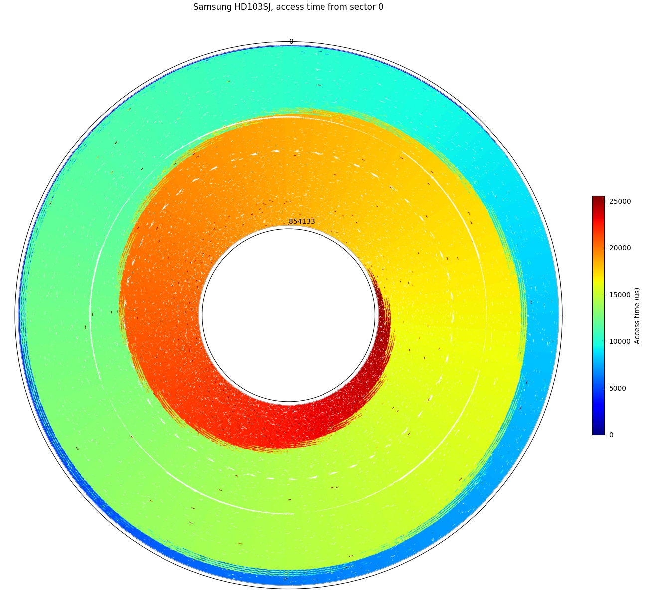
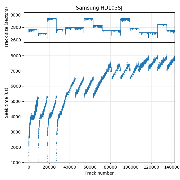
Full-disk access time: Furthest sector is just over 3 revolutions away.

Track sizes: This drive switches heads/surfaces infrequently.
The track size plot shows that different recorditng surfaces have different track sizes. Head (surface) changes occur around every 9000 tracks, which is much less frequently than other drives.
Seek profile, first 140,000 tracks. There are 4 recording surfaces. This disk switches surfaces infrequently (note the x-axis scale), and different surfaces have different track sizes.

Track skew: All track start sectors are aligned to a multiple of 72° (1/5 revolution)
This drive has four recording surfaces. All tracks are always laid out from outside towards inside without reversing, while the pattern of track sizes show that the sequence of surfaces used repeats every 4 serpentines without reversing, thus it uses a type FF track layout.
The track skew is 72°, and appears to be exactly 1/5 revolutions. There are a small number of skews that are greater (144° and 288° seem prominent), but these seem random and not associated with serpentine boundaries.
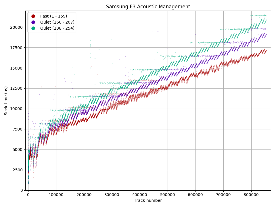
Seek profile and acoustic management: Four recording surfaces are visible, and there are three AAM levels.
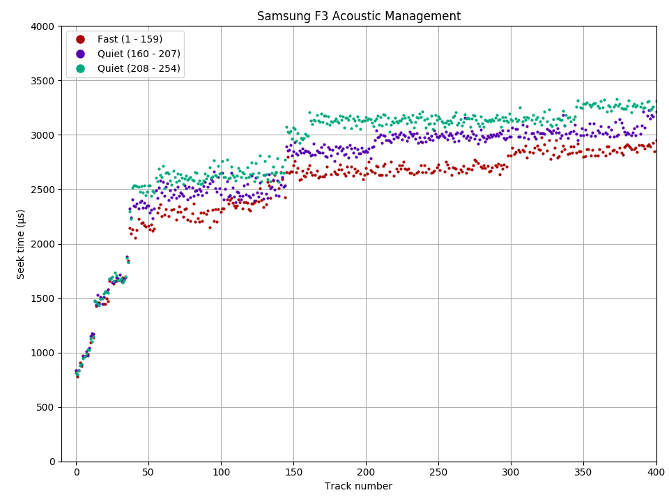
Acoustic management does not affect the seek time for short-distance (about 36 tracks, 2 ms) seeks.
The SpinPoint F3 has three levels of acoustic management, which affects the seek time for long-distance seeks. As expected, short-distance seeks (around 2 ms or less) are always the same speed.
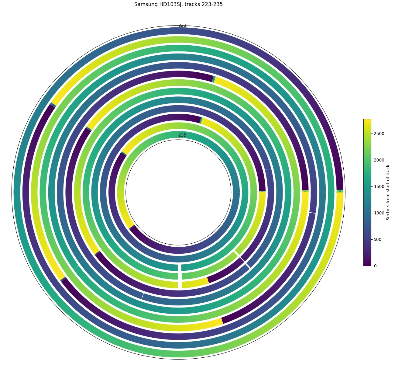
Angular position, tracks 223 – 235. There are a few holes in this plot, the biggest of which is in tracks 231-233.
This plot of tracks 223 – 235 shows an example of defective sectors causing holes. The biggest hole is on tracks 231 – 233.
Hitachi 7K1000.C, 1 TB
| Hitachi 7K1000.C | |
|---|---|
| Capacity | 1 TB |
| RPM | 7200 |
| Sectors (512B) | 1953525168 |
| Sectors per track | 2673 – 1350 |
| Tracks | 914873 |
| Surfaces | 4 |
| Skew (°, rev) | 53.3° (4/27 rev) |
| Max. seek (ms) | 15.2 |
| Random access (ms) | – |
| Random seek (ms) | – |
| Avg. track pitch (TPI) | 207k |
| Avg. OD linear density (kbpi) | 970 |
| Track layout | |
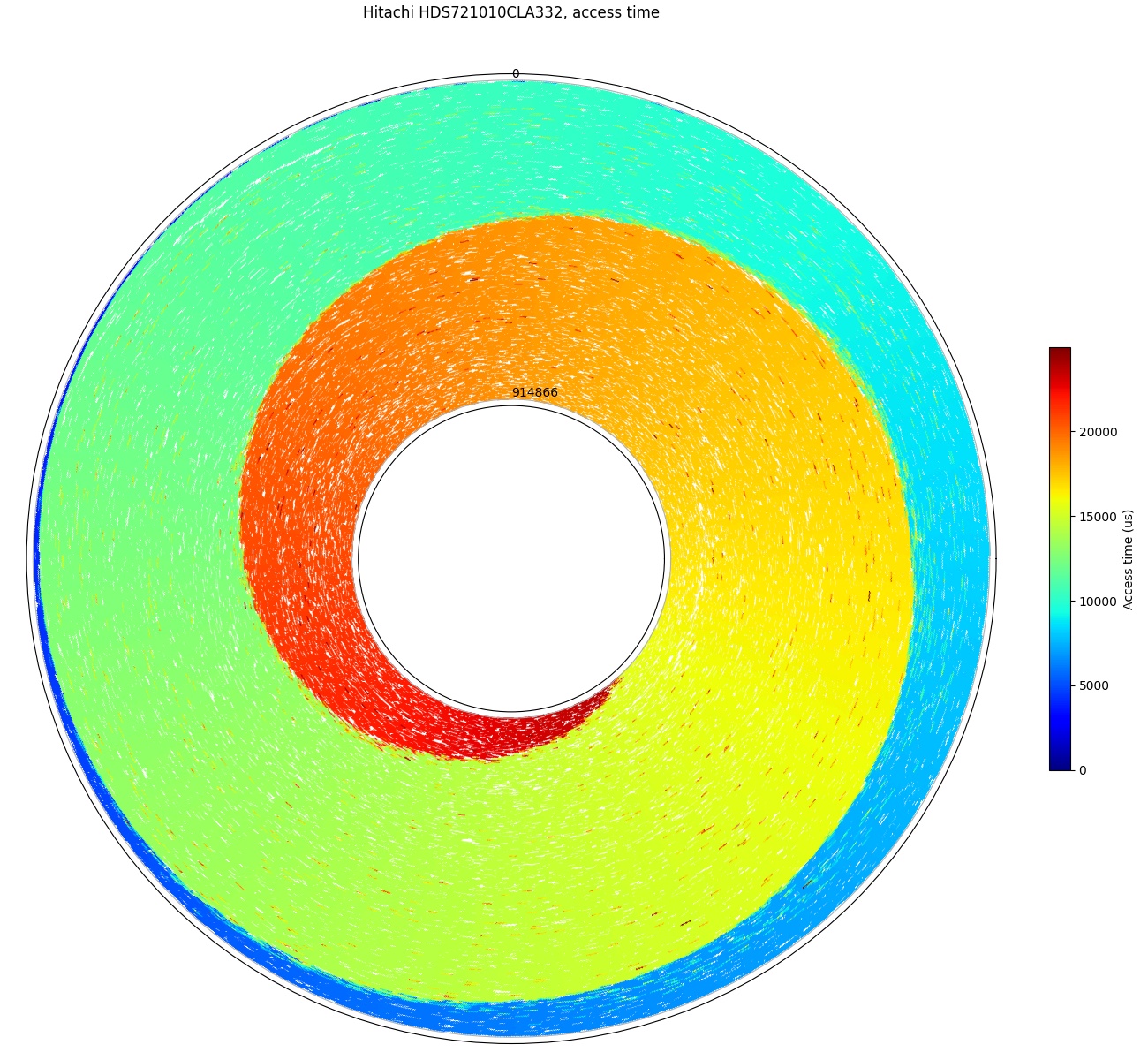
Full-disk access time: Furthest point is less than 3 revolutions away.
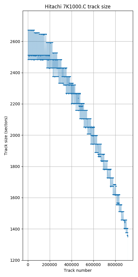
Track sizes
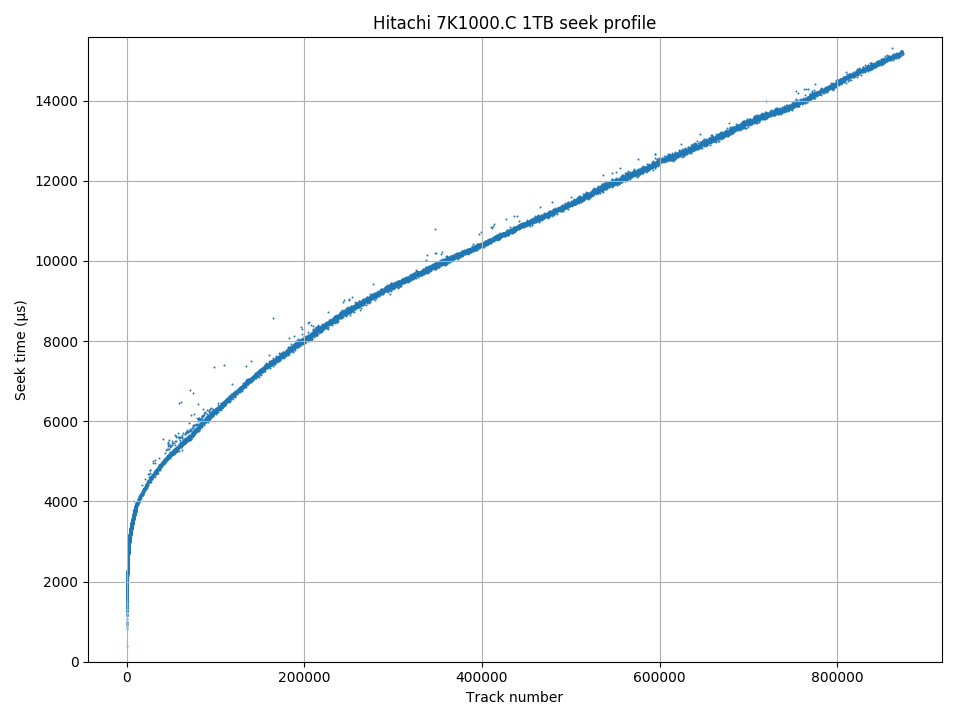
Seek profile
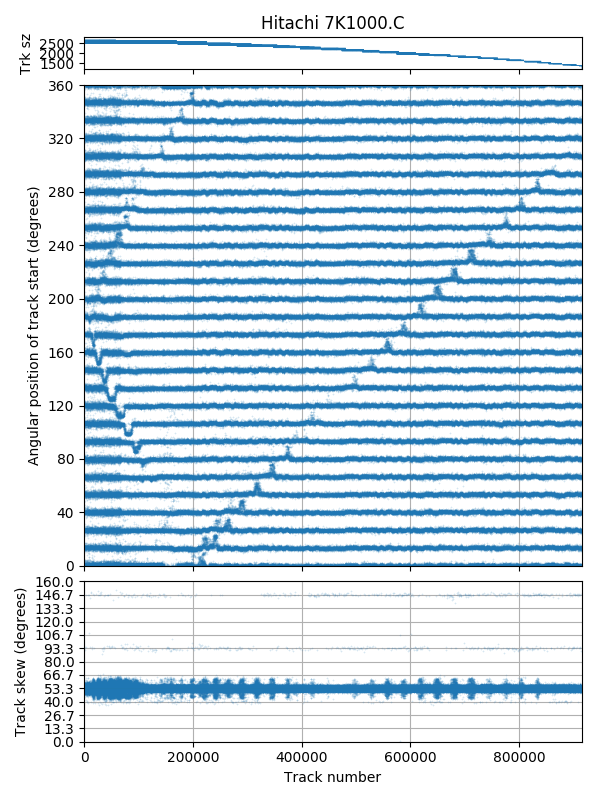
Track skew: I don’t know what that pattern is.
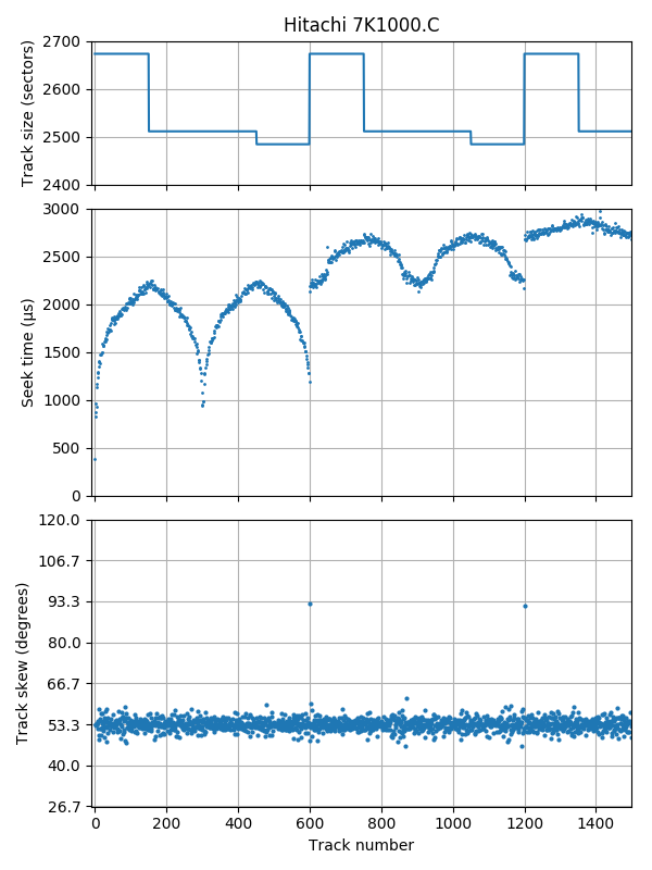
Seek profile and skew, first 1400 tracks: Layout is 4-surface surface serpentine.
The track skew appears to be 53.3° (exactly 4/27 revolutions). There is a pattern in the plot that superficially resembles the pattern seen in the Seagate 7200.9 (a pattern related to the seek time), but I have not investigated into what it is.
Plotting the track size and seek profile on the same plot easily shows the track layout. There are four surfaces, using a seek-first type AF layout. There is a track skew of 93.3 (7/27 revolutions) after each set of four serpentines where there is a bigger seek required to reach the beginning of the next serpentine.
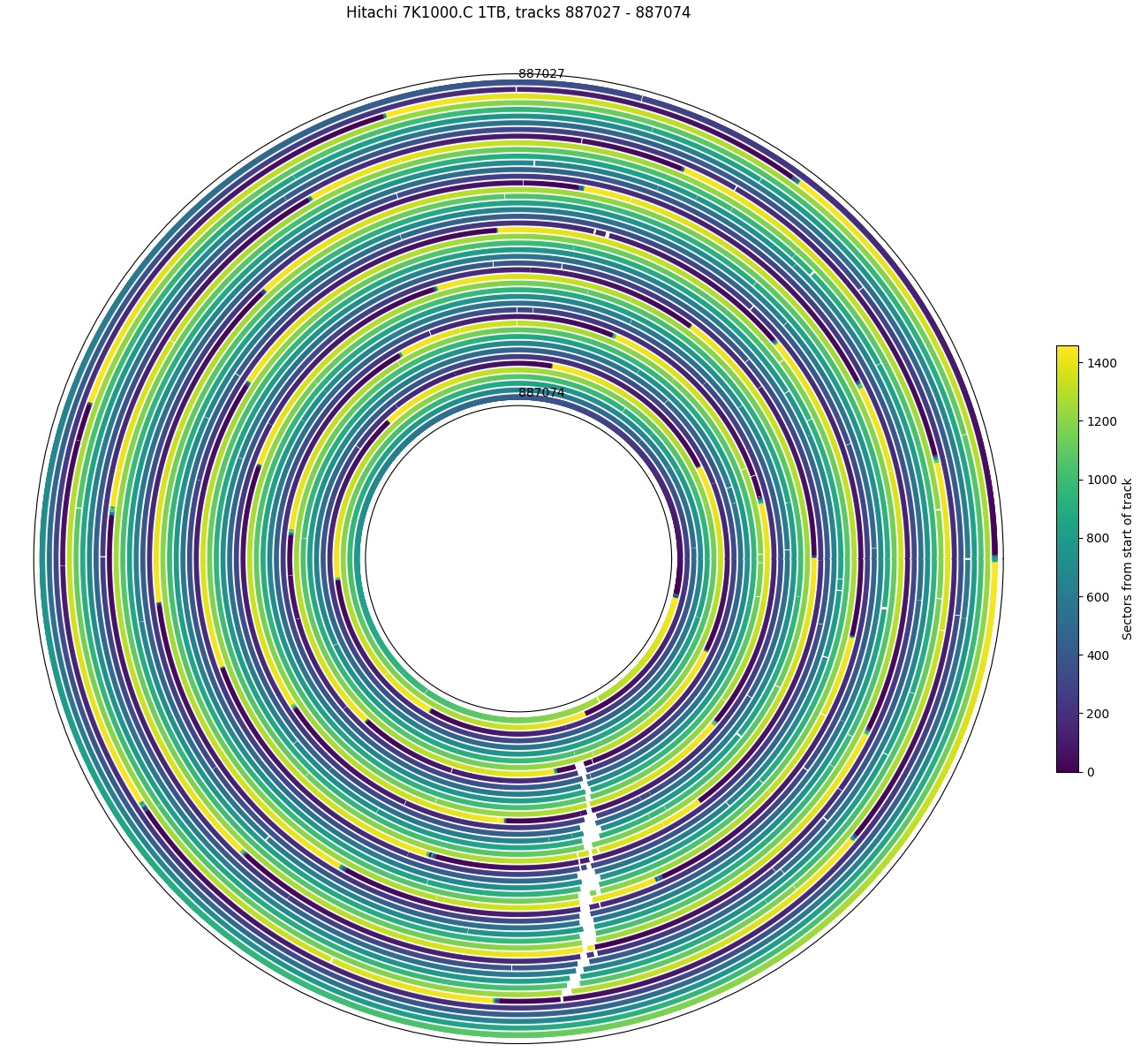
Angular position tracks 887,027 – 887,074. Hole spanning 35 tracks.
This plot is an example of a hole of defective sectors that spans 35 consecutive tracks.
Toshiba P300, 3 TB
| Toshiba DT01ACA300 and P300 | |
|---|---|
| Capacity | 3 TB |
| RPM | 7219.1 7200.3 7200.0 7200.0 |
| Sectors (4096B) | 732566646 |
| Sectors per track | 473 – 211 464 – 204 485 – 207 464 – 216 |
| Tracks | 2,075,497 ~2,098,859 2,070,465 2,076,586 |
| Surfaces | 6 |
| Skew (°, rev) | 37.2° (3/29 rev) |
| Max. seek (ms) | 21.0 21.1 20.9 20.9 |
| Random access (ms) | 15.3 |
| Random seek (ms) | 10.8 |
| Avg. track pitch (TPI) | 313k |
| Avg. OD linear density (kbpi) | 1400 |
| Track layout | |
I tested four drives of this model. Two were sold as P300 (model HDWD130), while two were sold as model DT01ACA300. As far as I can tell, these two drive models are identical. Some of the measurements in the box to the right are listed four times, once for each drive. When four results are listed, the first two are the older DT01ACA300 drives, while the latter two are the newer P300 drives.

Full-disk access time: Furthest sector is about 3.5 revolutions away.
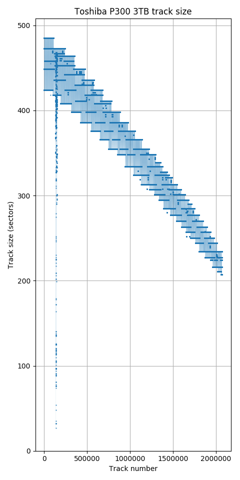
Track sizes: The region near track 140,000 is a region with many defective sectors causing the track size to drop.
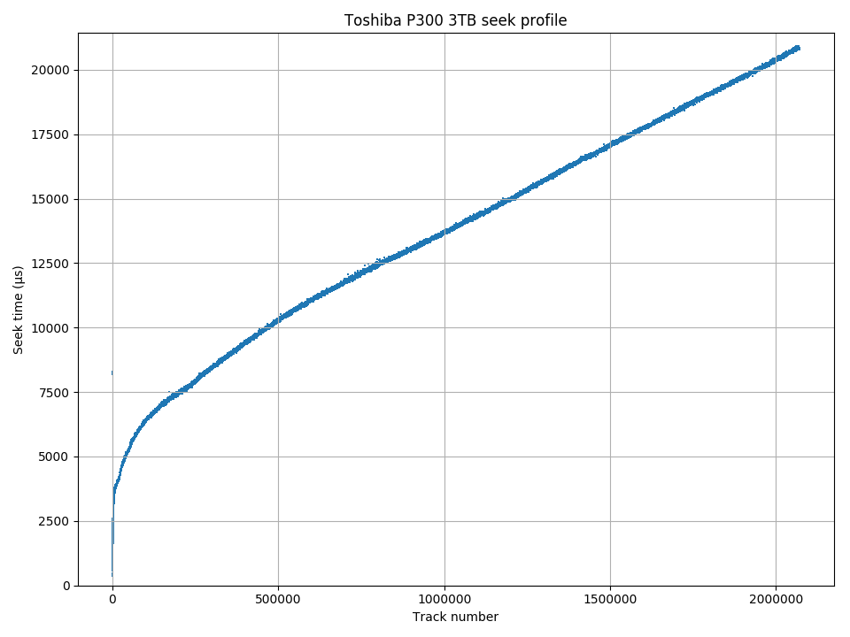
Seek profile
The Toshiba P300 is unusual in having huge holes due to defective sectors. The hole can be big enough it is obvious on the track size plot. The most visible hole in the above plot is between tracks 130,000 and 155,000, where several tracks dropped to around 30 sectors remaining (from around 450). Of the four drives of this model, two (one DT01ACA300, one P300) had this kind of defective region where most of the sectors were bad. The presence of so many manufacture-time defects does not seem to have caused any post-manufacturing defects. All four drives still have no new bad sectors after 13,000 to 30,000 power-on hours.
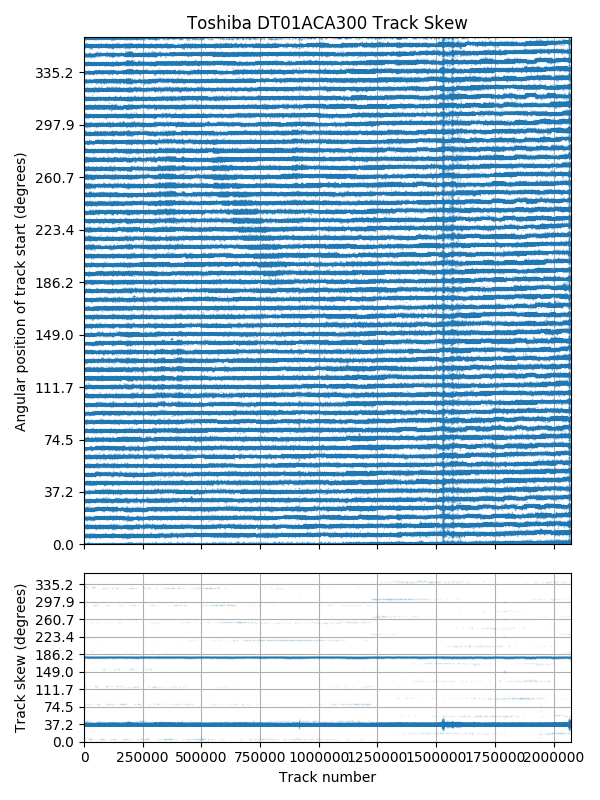
Track skew is exactly 3/29 revolutions.
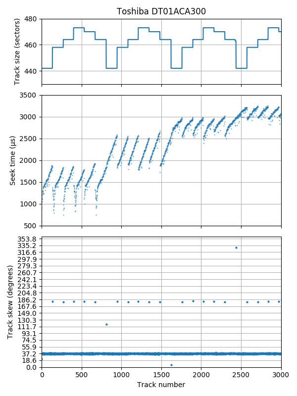
Seek profile and skew, first 3000 tracks. There are 6 surfaces, using a seek-first FF layout.
The track skew appears to be 37.2° (exactly 3/29 revolutions). There is a 180° skew at serpentine boundaries, but the skew after every 6 serpentines appears to be unpredictable. The drive has 6 surfaces. The track layout is type FF. Tracks are always arranged outside to inside on all serpentines, and the order of surfaces repeats without reversing, as seen in the track-size portion of the zoomed-in plot.
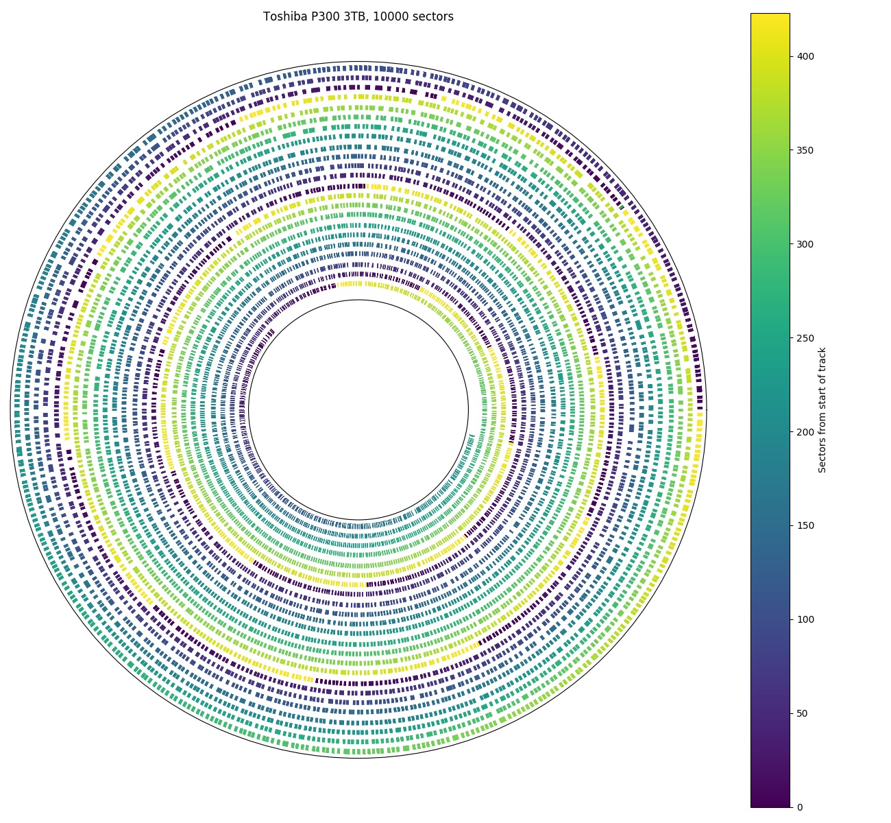
Angular position, first 10000 sectors. 37.2° track skew.
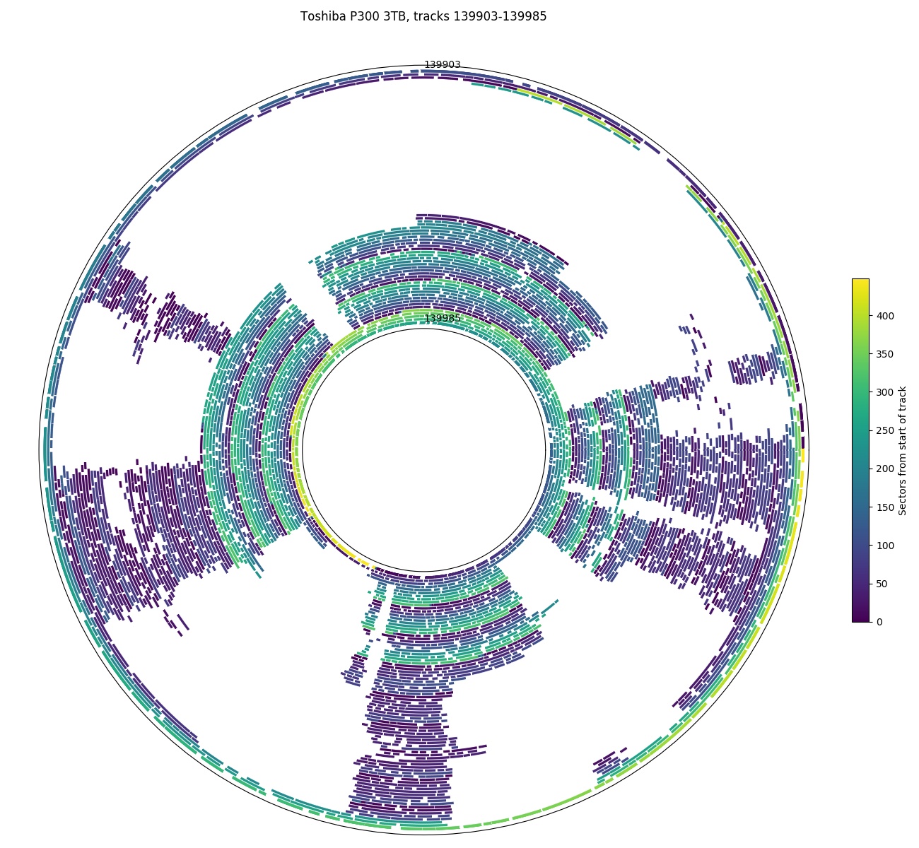
Angular position, tracks 139,903 – 139,985. Most of the sectors are defective here.

Track size for the same region as the hole shown in the previous plot (tracks 139,903 – 139,985)
The above three plots show a region of the disk with many defective sectors. The first of the three shows a region with no defects (the first 10,000 sectors of the drive) for comparison. The second plot shows a region of the disk where about 76% of the sectors are defective (tracks 139,903 – 139,985). The third plot shows the track sizes for the same region. In this particular zone, it appears the normal number of sectors per track is 467. The hole causes more than 30 tracks to have less than 100 sectors, with one track as low as 74 sectors.
Toshiba X300, 5 TB
| Toshiba X300 HDWE150 | |
|---|---|
| Capacity | 5 TB |
| RPM | 7200 |
| Sectors (4096B) | 1220942646 |
| Sectors per track | 500 – 229 |
| Tracks | 3279583 |
| Surfaces | 10 |
| Skew (°, rev) | 22.5° (1/16 -0.000008 rev) |
| Max. seek (ms) | 14.6 |
| Random access (ms) | 12.1 |
| Random seek (ms) | 7.9 |
| Avg. track pitch (TPI) | 298k |
| Avg. OD linear density (kbpi) | 1450 |
| Track layout | |
The Toshiba X300 5 TB hard drive is a 5-platter (1 TB/platter) drive. This is the same density as the 3-platter 3 TB Toshiba P300, which may lead to the expectation that it’s the same drive, just with two more platters. However, they are clearly different designs. The X300 has much faster seeks, both for short and long distance. Probably due to the faster seek time, the X300 also has a smaller track skew (22.5° vs. 37.2°). It also uses a different track layout than the P300, and does not have giant holes of defective sectors (it doesn’t seem to have any holes). In short, it appears to differ in nearly every metric except platter density.

Full-disk access time: Furthest sector is about 2.75 revolutions away.
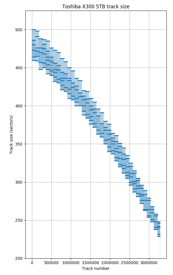
Track sizes
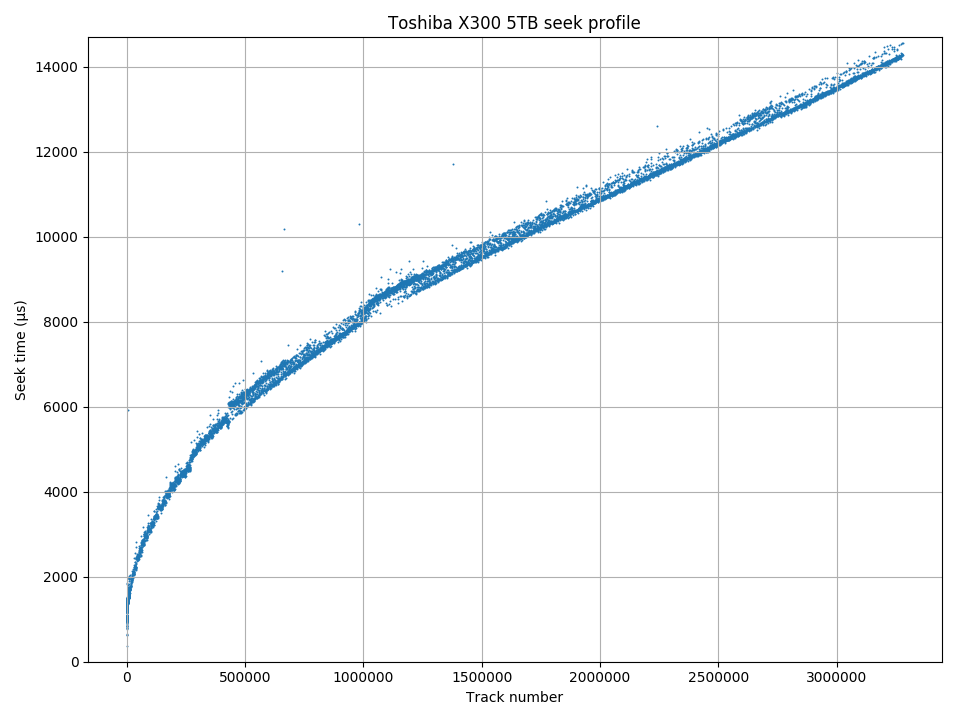
Seek profile
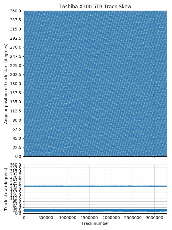
Track skew: not exactly 1/16 revolution.
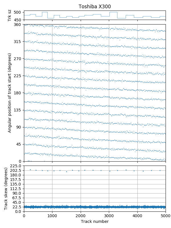
Track skew, first 5000 tracks. 22.5° skew, but 202.5° skew at serpentine boundaries.
The track skew is very slightly less than 22.5° (1/16 revolution), with a 202.5° skew at serpentine boundaries.
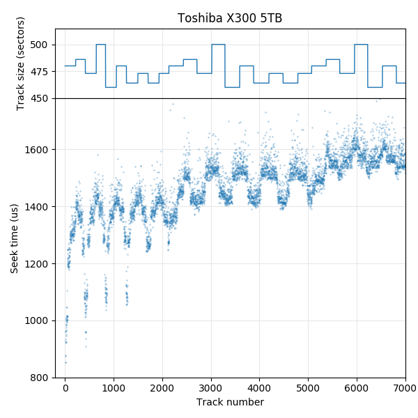
Seek profile and track size, first 7000 tracks: 10 recording surfaces.
Zooming in to the seek profile shows that this drive has 10 surfaces (5 platters), and uses a surface serpentine (type AF) track layout. Looking at the sequence of track sizes show the sequence repeating every 10 surfaces, without reversing the sequence.
There does not appear to be any tracks with missing sectors due to defects. However, there are many examples where the serpentines size does not appear to be regular. It seems that this drive only uses track slipping to handle defects.
Very nice.
Thanks!
Really good. Thanks for sharing!
this is an amazing article.how long did it take you to write it ? just curious.
Thanks! It took about a year (with some extended breaks) between starting to write the microbenchmarks and finishing writing. Writing (while collecting the final data) took about three months.
Hi! Really nice. This has educational value, too. I’m running this on a hard disk with the intent to show this to my kids.
I have a few questions.
First, are some measurements (even mildly) stressing for the device? Should I avoid performing any on a healthy disk with live data?
Second, I’ve looked at the source code, it produces table-formatted logs, but nothing looking like a plot or a source+data script for a plotting program. What program do you use to generate plots? R? Something else? Can you share any script, even something raw that would need manual steps? I may be willing to adjust them and/or do some integration work for easier use and git it back.
Third, I don’t see any license text in the source code. Have you considered an open-source license? It would be great!
Fourth, have you considered an alternative to requiring the user to explicitly provide a sector range, and instead mean “all disk area”? Current state would require manual copy-paste for each drive or a wrapper script. Are you open to contributions to provide a convention like value ‘-1’ means “automatic” (e.g. 0 for “start”, last sector number for “end”, some relevant value for “steps”).
Thanks a lot!
Thanks! Hm, what value does this have other than “educational value”? 🙂
1. Even powering on a hard drive is stressing for it, so… “yes”. That said, I was comfortable enough to run this on all of my disks with live data, grinding away for days. One disk failed (the 1″ Seagate microdrive), but that drive was already failing when I bought it, as seen by the seek errors. I also had a Seagate Barracuda II (19 years old) die from just being powered on and idle for a few hours, before I had a chance to test it. It very obviously overheated, but I don’t know why. Do be careful if your disk is in an enclosure with no ventilation though.
2. I consumed the text output using Python + Matplotlib. That script is far too messy to publish. It was also annoyingly slow at generating plots (up to a minute). One thing that makes it easier to parse is that all of the output (except RPM) is a table with exactly two columns of numbers (everything after the second number on each line is for human consumption and ignored when plotting).
3. I haven’t given much thought to codifying exactly what license. I’m treating it as a research paper: Do what you want with it, cite as appropriate.
4. It’s not explicitly documented, but that’s how it works already. The sector numbers are 64-bit unsigned numbers (so -1 is big), then silently clamped to the size of the disk (all those CLAMPU macros…). I used “-1” in many of the example command line options scattered around the article.
hello sorry for my bad english good aticle but very hard xD I haven’t understand all ^^
I have a die seagate 1To and with testdisk ( https://www.cgsecurity.org ) he detect bad size and we can modified geometry but I don’t know CHS original can you help me to determinate it???
thanks a lot for all your work
Sorry, I don’t know any magic that can recover data from a dying disk.
1 TB disks don’t use CHS at all. CHS can only address at most ~130 GB, and most computers newer than 15-20 years don’t use CHS.
I’m not familiar with how TestDisk works, but the geometry setting probably doesn’t matter: https://forum.cgsecurity.org/phpBB3/viewtopic.php?t=6618
sorry I see the button reply only now …
thanks a lot for your answer !
I know the new disk don’t use CHS but they simulate it?
when they run test disk it speak disk capacity must be correctly detected for a successful recovery
and the only method I have find for it is modify CHS (in the forum they speak in many thread about modify geometry xD)
in any case it will have allowed me to discover many thread interesting with another which explains that even formatting leaves data in a sector of 63 bit (in beginning of each partition) and in sector at the end of normal capacity!!
have a good time for christmas holiday
PS sorry for my bad english
Great!
BTW, thought about a Windows version of the tool? My disks I want to test are in a “remote” Windows server.
I adapted the code to run under cygwin. Then I also changed unix calls (pread()) to native Windows calls, but the HDD cache is interfering. Not sure if it can be turned off in Windows.
Nice 🙂
I think it’s likely that it is possible to send commands straight to the disk, but I haven’t tried looking for it, and don’t know how to do so…
Another idea for enhancement:
– detect if the disk uses SMR (Shingled Magnetic Recording)
– detect parameters of SMR (band size, etc…)
Hi David,
I don’t think I’ll be working on a Windows version anytime soon. It’ll take effort to figure out how to do sector reads and turn off the cache in Windows…
I’ve never owned a SMR drive, so I haven’t tried microbenchmarking one. Someone else did though: http://www.ccs.neu.edu/home/pjd/papers/skylight-tos.pdf (Aghayev, Shafaei, and Desnoyers, “Skylight — A Window on Shingled Disk Operation”). According to their results on a few Seagate drives (which use a static mapping), the data layout is essentially identical to conventional drives for data that isn’t located in the persistent cache. It might turn out to be near-impossible to detect SMR without writing to the drive.
Hello there again!
Do you know of a tool that measure the disk cache size?
I don’t know of one, but it seems plausible to write one. Reading sectors using pread does perform differently when the cache is enabled, so it should be possible to come up with some sequence of pread that tells you something about the cache.
This was a great and accurate job!
My best compliments.
It would be nice to have also a set of script to do all tests in batch and generate the plots…
I’d like to know how a OS like Windows discovers the size of a Hard drive, before formating it.
I think it eventually boils down to sending a IDENTIFY_DEVICE command to the drive (for an ATA device).
See words 60-61 and 100-103 of the IDENTIFY_DEVICE response in the ATA command set specification.
SCSI has a READ CAPACITY command.
um, what about hybrid sshd ?
There’s no reason to expect the hard disk in a SSHD would be any different from a standard hard drive. It’s just a flash memory cache on top.
Dear Henry
I skimmed through this particiuar blog
Graet work
I recently looked t the paper at the storage conference which won the best paper award
https://www.msstconference.org/MSST-history/2024/Papers/msst24-1.1.pdf
The paper does a nice integraion to show that in a simplified zoned diks
–whitch # of bytes per track prop to radius the mean seek distance is les than 1/3 (times # of cylinderes)
Of course one is interested i high perf diaks whih are short striked
You gave a graoph which shows depending ib IOS very smaall frction of a disk is used
Back in 1997 see the TPDS paper in dblp — I dealt with a disk with two zones
In 2007 pulisheda paper with general anlysis
This analysis required theinfo about different zones — how many tracks per zone 1 <= i <- I how any sectors per track in ith zone t_i
Such results were published here
https://www.pdl.cmu.edu/DiskSim/diskspecs.shtml
I guess you can generate such a table
Can you repond by email or least rell me thta you have responded
Best
Alex
PS Too bad I am retired and cannot grant you a PhD
Hi Henry,
Just stumbled on your work and find it amazing!
Thanks for publishing your results and the code.
/Marc